Download

1 / 19
210 likes | 411 Views
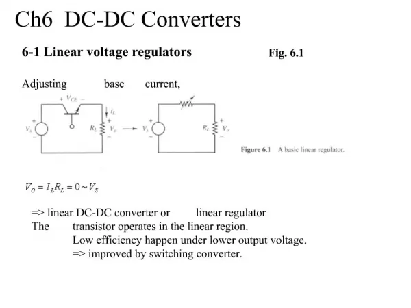
EE462L, Fall 2012 PI Voltage Controller for DC-DC Converters. !. PI Controller for DC-DC Boost Converter Output Voltage. Open Loop, DC-DC Converter Process. Hold to 90V. error. V. pwm. PWM mod. . DC. -. DC . PI . V. out. V. and MOSFET . conv. controller. set. +. driver. –.

E N D
! PI Controller for DC-DC Boost Converter Output Voltage Open Loop, DC-DC Converter Process Hold to 90V error V pwm PWM mod. DC - DC PI V out V and MOSFET conv. controller set + driver – (scaled down to about 1.3V) DC-DC Converter Process with Closed-Loop PI Controller
Proportional Integral Our existing boost process The Underlying Theory Hold to 90V error V pwm PWM mod. DC - DC PI V out V and MOSFET conv. controller set + driver – (scaled down to about 1.3V)
! Theory, cont. error e(t) V pwm PWM mod. DC - DC PI V out V and MOSFET conv. controller set + driver – • Proportional term: Immediate correction but steady state error (Vpwm equals zero when there is no error (that is when Vset = Vout)). • Integral term: Gradual correction • Consider the integral as a continuous sum (Riemman’s sum) • Thank you to the sum action, Vpwm is not zero when the e = 0 • Has some “memory”
E.g. Buck converter • Vin = 24 V • Vout = 16 V (goal) • L = 200 uH, C = 500 uF, R = 2 Ohm
! E.g. Buck converter • Vin = 24 V • Vout = 16 V (goal) • L = 200 uH, C = 500 uF, R = 2 Ohm • Ki = 40, Kp = 0 iL vC d e
! E.g. Buck converter • Vin = 24 V • Vout = 16 V (goal) • L = 200 uH, C = 500 uF, R = 2 Ohm • Ki = 10, Kp = 0 iL vC d e
! E.g. Buck converter • Vin = 24 V • Vout = 16 V (goal) • L = 200 uH, C = 500 uF, R = 2 Ohm • Ki = 0, Kp = 1 iL vC d e
! E.g. Buck converter • Vin = 24 V • Vout = 16 V (goal) • L = 200 uH, C = 500 uF, R = 2 Ohm • Ki = 0, Kp = 0.1 iL vC d e
! E.g. Buck converter • Vin = 24 V • Vout = 16 V (goal) • L = 200 uH, C = 500 uF, R = 2 Ohm • Ki = 10, Kp = 1 iL vC d e
work! = = z = T 0 . 8 T K 0 . 45 0 . 65 i p Theory, cont. Recommended in PI literature From above curve – gives some overshoot
Mostly Integral Control - Oscillation 90V Improperly Tuned PI Controller Mostly Proportional Control – Sluggish, Steady-State Error 90V
! · V = K(V − V ), K large (hundreds of thousands , or one million ) out + − · I = I = 0 + − · Voltages are with respect to power supply ground (not shown) · Output current is not limited Op Amps I − V – − V out I + V + + Assumptions for ideal op amp
! + = V KV KV out out in K + = = · V ( 1 K ) KV V V out in out in + 1 K = V V out in Example 1. Buffer Amplifier(converts high impedance signal to low impedance signal) = - V K ( V V ) = K(Vin – Vout) out + − – V out V + in K is large
! Example 2. Inverting Amplifier(used for proportional control signal)
æ ö V b = - = - ç ÷ V K ( V V ) K V + - - out 2 è ø V V b out = - V - 2 K ! - - V V V V - - a out + = 0 R R + V V a out - + - = = V V V V 0 V - - - a out 2 V - + - - æ ö æ ö æ ö V V V V V V æ ö V V K b a out out b a b a = - + = + = ç ÷ ç ÷ ç ÷ ç ÷ V K V K K V 1 K out out out 2 2 2 2 2 2 è ø è ø è ø è ø ( ) = - - V V V out a b Example 3. Inverting Difference(used for error signal) , so . KCL at the – node is , so , yielding . Eliminating yields , so , or . For large , then K
- V out = - = - = V K ( 0 V ) KV V - - - out K ! - - - V V V V V V - - - a b out + + = 0 R R R = + + 3 V V V V - a b out - - æ ö V æ ö 3 out = + + - = + ç ÷ ç ÷ V 3 V V V V 1 V V - a b out out a b K K è ø è ø ( ) = - + V V V out a b Example 4. Inverting Sum(used to sum proportional and integral control signals) , so . KCL at the – node is , so . Substituting for yields , so . Thus, for large , K
~ ~ = - V K ( 0 V ) - out ~ V ~ out = - V - K ~ ~ ~ ~ - - ! V V V V - - in out + = 0 1 R i w j C ~ - V ~ out - ~ V æ ö in - V ~ ~ K out ç ÷ + w - = j C V 0 V - ç ÷ out R K è ø i ~ æ ö - V æ ö 1 1 ~ in ç ÷ - w + = ç ÷ V j C 1 ç ÷ out KR K R è ø è ø i i ~ - V ~ ~ ~ ( ) in = - w = V V j R C V out out i in w j R C i ~ V R i out Example 5. Inverting Integrator(used for integral control signal) Using phasor analysis, , so . KCL at the − node is . Eliminating yields . Gathering terms yields æ ö - æ ö 1 1 ~ ~ ç - w + ÷ = ç ÷ , or For large , the K V j R C 1 V ç ÷ out i in K K è ø è ø expression reduces to , so (thus, negative integrator action). For a given frequency and fixed , increasing reduces the magnitude of . C
Op Amp Implementation of PI Controller Signal flow – error R p αV o ut + – – – 15kΩ + V pwm – + Difference + V set Proportional (Gain = −1) + Summer (Gain = − K ) p (Gain = −1 1) Buffers (Gain = 1) C i R i R is a 500kΩ pot, R is a 100kΩ pot, and all other i p – resistors shown are 100kΩ, except for the 15kΩ resistor. + Inverting Integrator 4 The 500kΩ pot is marked “504” meaning 50 • 10 . (Time Constant = T ) i 4 The 100kΩ pot is marked “104” meaning 10 • 10 . (Note – net gain K is unity when, in the open loop condition and with the integrator disabled, p V is at the desired value) pwm