Download
1 / 62
620 likes | 795 Views
Positioning for the Shoulder Girdle. By Prof. Jarek Stelmark. Shoulder Girdle Anatomy Review.

E N D
Positioning for the Shoulder Girdle By Prof. Jarek Stelmark
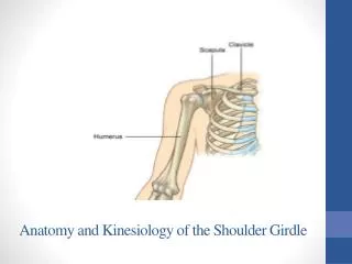
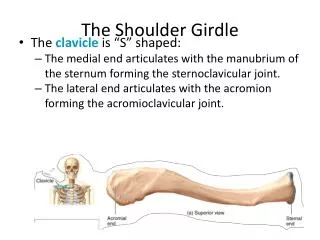
Shoulder Girdle Anatomy Review The shoulder girdle consists of two bones: the clavicle and the scapula. The function of the clavicle and scapula is to connect each upper limb to the trunk or axial skeleton. Anteriorly, the shoulder girdle connects to the trunk at the upper sternum, but posteriorly, the connection to the trunk is incomplete because the scapula is connected to the trunk by muscles only.
Clavicle Each shoulder girdle and each upper limb connects at the shoulder joint between the scapula and the humerus. Each clavicle is located over the upper anterior rib cage. Each scapula is situated over the upper posterior rib cage. The upper margin of the scapula is at the level of the second posterior rib, and the lower margin is at the level of the seventh posterior rib (T7). Note that the lower margin of the scapula corresponds to T7, also used as a landmark for location of the central ray for chest positioning
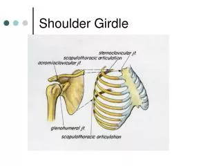
A.Sternoclavicular joint B.Sternal extremity C.Body D.Acromial extremity E.Acromioclavicular joint
A.Acromion B.Neck of scapula (about 1 inch below the coracoid process) C.Scapular notch D.Superior angle E.Medial (vertebral) border F.Inferior angle G.Lateral (axillary) border H.Glenoid cavity (fossa) or scapulohumeral joint
A.Acromion B.Coracoid process C.Inferior angle D.Spine of scapula E.Body of scapula
AP PROJECTION—EXTERNAL ROTATION: SHOULDER (NONTRAUMA) Warning: Do NOT attempt to rotate arm if fracture or dislocation is suspected! Pathology Demonstrated Fractures and/or dislocations of the proximal humerus and shoulder girdle are demonstrated. This projection may demonstrate calcium deposits in the muscles, tendons, or bursal structures. Some pathologies, such as osteoporosis and osteoarthritis, also may be demonstrated.
Part Position • Position patient to center scapulohumeral joint to center of IR. • Abduct extended arm slightly; then externally rotate arm (supinate hand) until epicondyles of distal humerus are parallel to IR. Central Ray • CR perpendicular to IR, directed to 1 inch (2.5 cm) inferior to coracoid • Minimum SID of 40 inches (100 cm) Note: The coracoid process may be difficult to palpate directly on most patients, but it can be approximated; it is about ¾ inch (2 cm) inferior to the lateral portion of the more readily palpated clavicle.
Full external rotation is evidenced by the greater tubercle visualized in full profile on the lateral aspect of the proximal humerus. Lesser tubercle is superimposed over humeral head.
Full internal rotation position is evidenced by the lesser tubercle visualized in full profile on the medial aspect of the humeral head. • An outline of the greater tubercle should be visualized superimposed over the humeral head.
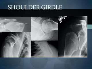
INFEROSUPERIOR AXIAL PROJECTION: SHOULDER (NONTRAUMA) (Lawrence Method) Warning: Do NOT attempt to rotate arm or force abduction if fracture or dislocation is suspected. Pathology Demonstrated: Osteoporosis, osteoarthritis, Shoulder dislocation.
Technical Factors • IR size—18 × 24 cm (8 × 10 inches), crosswise • Stationary grid (CR to centerline of grid, crosswise to prevent grid cutoff caused by CR angle) • 70 ± 5 kV range
Shielding • Place lead shield over pelvis and radiosensitive regions. • Patient Position • Position patient supine with shoulder raised about 2 inches (5 cm) from tabletop by placing support under arm and shoulder to place body part near center of IR. • Part Position • Move patient toward the front edge of tabletop and place a cart or other arm support against front edge of table to support abducted arm. • Rotate head toward opposite side, place vertical cassette on table as close to neck as possible, and support with sandbags. • Abduct arm 90° from body if possible; keep in external rotation, palm up, with support under arm and hand.
Central Ray • Direct CR medially 25° to 30°, centered horizontally to axilla and humeral head. If abduction of arm is less than 90°, the CR medial angle also should be decreased to 15° to 20° if possible. • Minimum SID is 40 inches (100 cm). Collimation Collimate closely on four sides. Respiration Suspend respiration during exposure
Structures Shown: • Lateral view of proximal humerus in relationship to the scapulohumeral cavity is shown. • Coracoid process of scapula and lesser tubercle of humerus will be seen in profile. • The spine of the scapula will be seen on edge below the scapulohumeral joint. Position: • Arm is seen to be abducted about 90° from the body. • The superior and inferior borders of the glenoid cavity should be directly superimposed, indicating correct CR angle. Collimation and CR: • Collimation should be visible on four sides to the affected shoulder. • CR and center of the collimation field should be at the axilla and the humeral head. Exposure Criteria: • Optimal density and contrast with no motion will demonstrate clear, sharp bony trabecular markings. • The bony margins of the acromion and distal clavicle will be visible through the humeral head.
INFEROSUPERIOR AXIAL PROJECTION: SHOULDER (NONTRAUMA) Clements Modification Central Ray • Direct horizontal CR perpendicular to the IR. • If the patient cannot abduct the arm 90°, then angle the tube 5° to 15° toward the axilla. • Minimum SID is 40 inches (100 cm).
SUPEROINFERIOR AXIAL PROJECTION: SHOULDER (NONTRAUMA) Central ray • Angled 5 to 15 degrees through the shoulder joint and toward the elbow. A greater angle is required when the patient cannot extend the shoulder over the IR.
POSTERIOR OBLIQUE POSITION—GLENOID CAVITY: SHOULDER (NONTRAUMA) Grashey Method Pathology Demonstrated Fractures and/or dislocations of the proximal humerus and fractures of the glenoid brim are demonstrated; erosion of glenoid rim, and the integrity of the scapulohumeral joint; also may demonstrate certain pathologies, such as osteoporosis and osteoarthritis.
Patient Position • Perform radiograph with the patient in an erect or supine position. (The erect position is usually less painful for patient, if condition allows.) Part Position • Rotate body 35° to 45° toward affected side. If the radiograph is performed with the patient in the supine position, place supports under elevated shoulder and hip to maintain this position. • Center mid-scapulohumeral joint to CR and to center of IR. • Adjust cassette so that top of IR is about 2 inches (5 cm) above shoulder and side of IR is about 2 inches (5 cm) from lateral border of humerus. • Abduct arm slightly with arm in neutral rotation. • Note: The degree of rotation varies depending on how flat or round the shoulders of the patient are. Having a rounded or curved shoulder and back requires more rotation to place the body of the scapula parallel to the IR.
Central Ray • CR perpendicular to IR, centered to scapulohumeral joint, which is approximately 2 inches (5 cm) inferior and medial from the superolateral border of shoulder • Minimum SID of 40 inches (100 cm)
Structures Shown: • Glenoid cavity should be seen in profile without superimposition of humeral head. Position: • The scapulohumeral joint space should be open. Anterior and posterior rims of glenoid cavity are superimposed. Collimation and CR: • Collimation should be visible on four sides to area of affected shoulder. • CR and center of the collimation field should be at the midglenohumeral joint. Exposure Criteria: • Optimal density and contrast with no motion will visualize soft tissue margins and clear, sharp bony trabecular markings. • Soft tissue detail of the joint space and axilla should be visualized.
SHOULDER -SCAPULAR Y LATERAL—ANTERIOR OBLIQUE POSITION: SHOULDER (TRAUMA) Shoulder (trauma) • AP (neutral rotation) • Transthoracic lateral or • Scapular Y lateral
AP PROJECTION—NEUTRAL ROTATION: SHOULDER (TRAUMA) Pathology Demonstrated Fractures and/or dislocations of the proximal humerus and the shoulder girdle are demonstrated. Calcium deposits in the muscles, tendons, or bursal structures may be evident. Some pathologies, such as osteoporosis and osteoarthritis, also may be apparent.
Place patient's arm at side in “as is” neutral rotation. (Epicondyles generally are approximately 45° to plane of IR.)
TRANSTHORACIC LATERAL PROJECTION: PROXIMAL HUMERUS (TRAUMA) Lawrence Method Pathology Demonstrated Fractures and/or dislocations of the proximal humerus are demonstrated.
Pathology Demonstrated Fractures and/or dislocations of the proximal humerus and scapula are demonstrated. The humeral head will be demonstrated inferior to the coracoid process with anterior dislocations, and for less common posterior dislocations, the humeral head will be demonstrated inferior to the acromion process. Technical Factors • IR size—24 × 30 cm (10 × 12 inches), lengthwise
Part Position • Rotate into an anterior oblique position as for a lateral scapula with patient facing the IR. Average patient will be in a 45° to 60° anterior oblique position. Palpate scapular borders to determine correct rotation for a true lateral position of scapula. • Center scapulohumeral joint to CR and to center of IR. • Abduct arm slightly if possible so as to not superimpose proximal humerus over ribs; do not attempt to rotate arm. Central Ray • • CR perpendicular to IR, directed to the scapulohumeral joint (2 or 2½ inches [5 or 6 cm] below top of shoulder) • • Minimum SID of 40 inches (100 cm)
No dislocation Anterior dislocation
Structures Shown: • A true lateral view of the scapula, proximal humerus, and scapulohumeral joint. • Position: • The thin body of the scapula should be seen on end without rib superimposition. • The acromion and coracoid processes should appear as nearly symmetric upper limbs of the Y. • The humeral head should appear superimposed over the base of the Y if the humerus is not dislocated. • Collimation and CR: • Collimation is visible on four sides to area of affected shoulder. • CR and center of the collimation field should be at the humeral head and surgical neck region. • Exposure Criteria: • Optimal density and contrast with no motion will visualize sharp bony borders and the outline of the body of the scapula through the proximal humerus.
AP PROJECTION: AC JOINTS Bilateral With and Without Weights Warning: Shoulder and/or clavicle projections should be completed first to rule out fracture, or this radiograph may be taken without weights first and checked before it is taken with weights.
Technical Factors • IR size—35 × 43 cm (14 × 17 inches), crosswise, or 7 × 17 inches (14 × 43 cm), if available • “With weight” and “without weight” markers • Bucky or non-grid (depending on size of shoulder) • AEC not recommended • 65 ± 5 kV with screen; 65-70 kV with grid on larger patients • For broad-shouldered patients, two 18 × 24-cm (8 × 10-inch) cassettes crosswise, placed side by side and exposed simultaneously to include both AC joints on a single exposure
Patient Position Perform radiograph with the patient in an erect position, posterior shoulders against cassette with equal weight on both feet; arms at side; no rotation of shoulders or pelvis; and looking straight ahead. (May be taken seated if patent's condition requires.) Two sets of bilateral AC joints are taken in the same position, one without weights and one stress view with weights.
Central Ray • CR perpendicular to a midpoint between AC joints, 1 inch (2.5 cm) above jugular notch • Minimum SID of 72 inches (180 cm)
Weights After the first exposure is made without weights and the cassette(s) has (have) been changed, for large adult patients, strap 8 to 10 pound minimum weights to each wrist, and, with shoulders relaxed, gently allow weights to hang from wrists while pulling down on each arm and shoulder. The same amount of weight must be used on each wrist. Less weight (5 to 8 pounds per limb) may be used for smaller or asthenic patients and more weight for larger or hypersthenic patients. (Check department protocol for the quantity of applied weights.) Note: Patients should NOT be asked to hold onto the weights with their hands; rather, the weights should be attached to the wrists so that the hands, arms, and shoulders are relaxed and possible AC joint separation can be determined. Holding onto weights may result in false-negative radiographs because they tend to pull on the weights, resulting in contraction rather than relaxation of the shoulder muscles
Alternate supine position: If patient's condition requires, the radiograph may be taken supine by tying both ends of a long strip of gauze to patient's wrists and placing around patient's feet with knees partially flexed, then slowly and gently straightening legs and pulling down on shoulders. Also may be performed by an assistant who gently pulls down on arms and shoulders.
Structures Shown: • Both AC joints, as well as the entire clavicles and SC joints, are demonstrated. Position: • Both AC joints are on the same horizontal plane. • No rotation occurred, as is evidenced by symmetric appearance of the SC joints on each side of the vertebral column. Collimation and CR: • Collimation should be visible on four sides, remembering to include both AC joints. • CR and center of the collimation field should be at the midpoint between the AC joints. Exposure Criteria and Markers: • Optimal density and contrast will clearly demonstrate the AC joints and soft tissue without excessive density. Bony margins and trabecular markings will appear sharp, indicating no motion. •Right and left markers, as well as markers indicating with and without weights, should be visible without superimposing essential anatomy.