Download
1 / 9
100 likes | 163 Views
Data Bus-bidirectional. Microprocessor. Memory. D1. D1. D2. Instruction Decoder. Arithmetic Logic Unit. Program Counter. Address Decoder. Address Bus. Data Bus-bidirectional. Microprocessor. Memory. D1. 0000. 35. D1. 20. D2. 37. Instruction Decoder. Arithmetic Logic

E N D
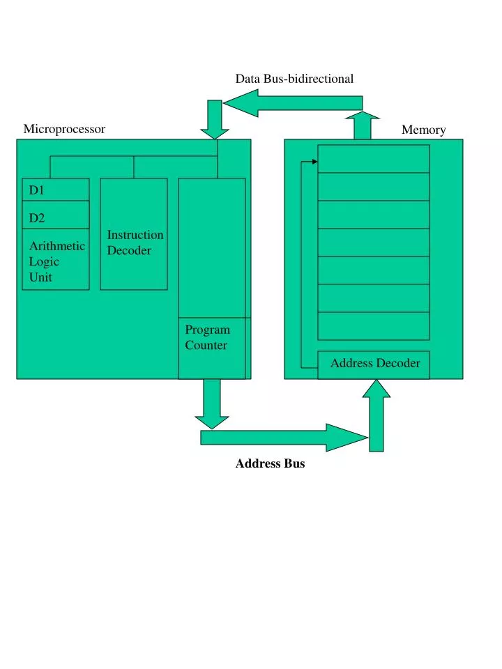
Data Bus-bidirectional Microprocessor Memory D1 D1 D2 Instruction Decoder Arithmetic Logic Unit Program Counter Address Decoder Address Bus
Data Bus-bidirectional Microprocessor Memory D1 0000 35 D1 20 D2 37 Instruction Decoder Arithmetic Logic Unit 10 73 Program Counter =0000 Address Decoder Address Bus Once assembled, the program is loaded into memory by a loader program • Start program with go 0000H • This loads Program Counter with 0000 • This travels along the Address bus to the address decoder • Once decoded it points to address 0000
Ah! 35 means move something into D0 – I need More info Data Bus-bidirectional 35 Microprocessor Memory D1 0000 35 D1 20 35 D2 Instruction Decoder 37 Arithmetic Logic Unit 10 73 Program Counter =0000 Address Decoder Address Bus 1st instruction goes ti the Instriction decoder. This unit decodes the instruction and decides if it needs any more information to complete the operation. In this It does – it requires the 20H.
Data Bus-bidirectional Microprocessor Memory D1 35 0001 D1 20 D2 37 Instruction Decoder Arithmetic Logic Unit 10 73 Program Counter =0001 Address Decoder 0001 -> Address Bus 4. The prgram counter is incremented, placed on the address bus and decoded.
Data Bus-bidirectional 20 Microprocessor Memory D1 35 0001 D1 = 20 20 D2 37 Instruction Decoder Arithmetic Logic Unit 10 73 Program Counter =0001 Address Decoder Address Bus 5. The value 20 is placed on the data bus and into the register D0. 6. The program counter is now incremented ready to point to the next instruction. This is the end of the first fetch cycle.
Ah! 37 means Move something into D1 – I need more info Data Bus-bidirectional 37 Microprocessor Memory D1 35 D1 = 20 20 37 0002 D2 Instruction Decoder 37 Arithmetic Logic Unit 10 73 Program Counter =0002 Address Decoder Address Bus • The cycle now repeats itself • The PC is placed onto the Address bus, it is decoded and the value 37 put • on the data bus. • This goes to the instruction decoder. This decides it need more info so it • requests more data. • Note. Inside the micro is a control unit which coordinates all the operations.
Data Bus-bidirectional 10 Microprocessor Memory D1 35 D1 = 20 20 D2 = 10 37 Instruction Decoder 0003 Arithmetic Logic Unit 10 73 Program Counter =0003 Address Decoder 0004 Address Bus 3. The PC is placed on the address bus and decoded 4. The data in address 0004 is sent to register D1
Ah! 73 means I must add D1 and D2. I now have All the info I need Data Bus-bidirectional 73 Microprocessor Memory D1 35 D1 = 20 20 73 D2 = 10 Instruction Decoder 37 Arithmetic Logic Unit 10 0004 73 Program Counter =0004 Address Decoder Address Bus 5. The PC is once again incremented to 0004,placed on the address bus and decoded. 6. The data (73) is placed on the data bus and goes to the Instruction decoder. It is decoded and the decoder knows that there is no more data required. The fetch cycle is now complete!
Data Bus-bidirectional 10 Microprocessor Memory D1 35 D1 = 20 20 73 D2 = 1030 37 Instruction Decoder Arithmetic Logic Unit 20+10 =30 10 0004 73 Program Counter =0004 Address Decoder 0004 Address Bus • The numbers are now added together. • This is the execute cycle.