Download
1 / 26
340 likes | 587 Views
Lecture 2: Antennas and Propagation. Anders Västberg vastberg@kth.se 08-790 44 55. Digital Communication System. Source of Information. Source Encoder. Channel Encoder. Digital Modulator. Modulator. RF-Stage. Channel. Information Sink. Source Decoder. Demodulator. RF-Stage.

E N D
Lecture 2: Antennas and Propagation Anders Västberg vastberg@kth.se 08-790 44 55
Digital Communication System Source of Information Source Encoder Channel Encoder Digital Modulator Modulator RF-Stage Channel Information Sink Source Decoder Demodulator RF-Stage Channel Decoder Digital Demodulator [Slimane]
Maxwell's Equations • Electrical field lines may either start and end on charges, or are continuous • Magnetic field lines are continuous • An electric field is produced by a time-varying magnetic field • A magnetic field is produced by a time-varying electric field or by a current
Radiation Only accelerating charges produce radiation [Saunders, 1999]
Electromagnetic Fields Poyntings Vector: Power density:
Impedance of Free Space • Both fields carry the same amount of energy • Free space impedance is given by • The power density can be expressed as [Slimane]
Antenna Gain • The antenna gain is defined by its relative power density
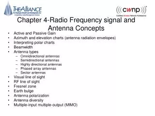
Propagation between two antennas (not to scale) No Ground Wave for Frequencies > ~2 MHz No Ionospheric Wave for Frequencies > ~30 Mhz
Diffraction [Saunders, 1999]
Diffraction • For radio wave propagation over rough terrain, the propagation is dependent on the size of the object encountered. • Waves with wavelengths much shorter than the size of the object will be reflected • Waves with wavelengths much larger than the size of the obstacle will pass virtually unaffected. • Waves with intermediate wavelengths curve around the edges of the obstacles in their propagation (diffraction). • Diffraction allows radio signals to propagate around the curved surface and propagate behind obstacles. [Slimane]
Propagation in the Atmosphere • The atmosphere around the earth contains a lot of gazes (1044 molecules) • It is most dense at the earth surface (90% of molecules below a height of 20 km). • It gets thinner as we reach higher and higher attitudes. • The refractive index of the air in the atmosphere changes with the Height • This affects the propagation of radio waves. • The straight line propagation assumption may not be valid especially for long distances. [Slimane]
Effective Earth Radius [Slimane]
Microwave Communication [Slimane]
Line-of-Sight Range [Slimane]
Fresnel Zone [Slimane]
Ionospheric Communication [Davies, 1993]
Propagation Modelling [Slimane]
L=l/2 I I Dipole antenna • Half-wave dipole • Gain 1,64 = 2.15 dBi • Linear Polarisation • Quarter-wave dipole • Conducting plane below a single quarter wave antenna. Acts like a half-wave dipole L=l/4 I
Corner Reflectors • Multiple images results in increased gain • Example:G=12 dBi Images l/2 Driven Element
Yagi-antenna 3-30 element and a gain of 8-20 dBi http://www.urel.feec.vutbr.cz/~raida/multimedia_en/chapter-4/4_3A.html
Loop-antenna • Linear Polarisation • Gain 1,76 dBi http://www.ycars.org/EFRA/Module%20C/AntLoop.htm
Parabolic antenna • Effective area Ae =hp d2/4 h=0.56 [Stallings, 2005]
Helical antenna • Normal mode • Axial mode http://hastingswireless.homeip.net/index.php?page=antennas&type=helical


![G3 - RADIO WAVE PROPAGATION [3 Exam Questions - 3 Groups]](https://cdn0.slideserve.com/484375/g3-radio-wave-propagation-3-exam-questions-3-groups-dt.jpg)


![G3 - RADIO WAVE PROPAGATION [3 Exam Questions - 3 Groups]](https://cdn1.slideserve.com/3333950/g3-radio-wave-propagation-3-exam-questions-3-groups-dt.jpg)