Download
1 / 19
190 likes | 446 Views
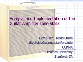
Analysis and Implementation of the Guitar Amplifier Tone Stack. David Yeh, Julius Smith dtyeh,jos@ccrma.stanford.edu CCRMA Stanford University Stanford, CA. Digital audio effects that emulate analog equipment are popular. “Modeling” amplifiers

E N D
Analysis and Implementation of the Guitar Amplifier Tone Stack David Yeh, Julius Smith dtyeh,jos@ccrma.stanford.edu CCRMA Stanford University Stanford, CA
Digital audio effects that emulate analog equipment are popular • “Modeling” amplifiers • Products by Line 6, Yamaha, Roland, Korg, Universal Audio, etc. • CAPS open source LADSPA suite • http://quitte.de/dsp/caps.html • Emulate behavior of classic analog gear in software • As close to real thing as possible • For portability and flexibility
Guitar amp tone stack is a unique component in the sound of an amplifier • Almost every guitar amplifier, solid state or tube, has a tone control circuit – referred to as a tone stack • Passive RC filter to audio signal • Located either directly after preamp stage or after stages of gain and buffer
Prior work • Modeled by Line 6 (and others) • Analyzed by Kuehnel (2005, book) • Substituted in CAPS (LADSPA plugins for guitar effects) by shelving filter
Parameter mapping from tone controls to frequency response is very complicated • Passive RC circuit • Three real poles • One zero at DC, one pair of zeros with anti-resonance • Shelving filter is close: 3 poles, 3 zeros • Frequency response depends on pole locations • But no notch filtering • Circuit components are not isolated • Component values are comparable • Bridge topology • Tone controls affect location of multiple poles and zeros
Tone Stack Transfer Function • Third order continuous time system • Complex mapping from component values/parameters to coefficients
Poles sweeping Bass and Mid Low freq Pole 1 Pole 2 Pole 3 High freq
Digitization as third-order filter • Straightforward approach • Find continuous time transfer function • Discretize by bilinear transform • Implement as transposed Direct Form II (DFII) • Pros: Perfect mapping of tone controls to frequency response within limitations of bilinear transform • Cons: Complicated formulas to compute coefficients
DFII block diagram Audio in Component values R, C Treble Compute DF coefs B[] Transposed DFII core A[] Mid Bass Audio out
DFII frequency response shows good match with continuous time version
Error relative to continuous time • Worst case errors shown • B=1, M=0, T=0 • Discrete time reaches low pass asymptote but continuous time does not
Reduced sampling rate • Commercial effects pedals commonly run at 31 kHz • Guitar amplifier system is bandlimited by speaker response: 100–6000 Hz. • For f_s = 20 kHz, error increases but only at high frequency because of asymptotic limits
Table lookup implementation simplifies computation of coefficients • Lattice filter implementation for robustness to roundoff error in coefficients and to smoothly fade between coefficients as tone controls are varied • Tabulate 25 steps of each tone control parameter • Convert from z-domain transfer function to lattice coefficients by step-down algorithm • Implemented DFII and lattice filter in CAPS audio suite. Both run in real time.
Sound samples • White noise at different settings • Original white noise (2 sec) • B=0 M=0 T=0 • B=0 M=1 T=0 • B=1 M=0 T=1 • B=1 M=1 T=0 • B=1 M=1 T=1 • B=0.5 M=1 T=0.5