Download
1 / 33
330 likes | 468 Views
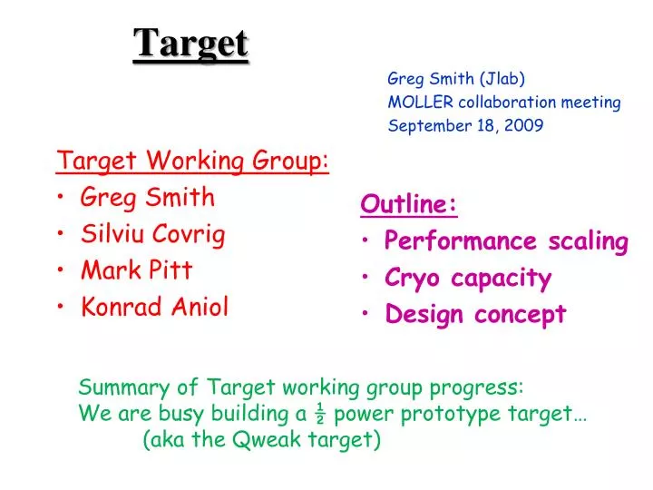
Target. Target Working Group: Greg Smith Silviu Covrig Mark Pitt Konrad Aniol. Greg Smith ( Jlab ) MOLLER collaboration meeting September 18, 2009. Outline: Performance scaling Cryo capacity Design concept. Summary of Target working group progress:

E N D
Target Target Working Group: • Greg Smith • SilviuCovrig • Mark Pitt • KonradAniol Greg Smith (Jlab) MOLLER collaboration meeting September 18, 2009 Outline: • Performance scaling • Cryo capacity • Design concept Summary of Target working group progress: We are busy building a ½ power prototype target… (aka the Qweak target)
Target Specifications • 150 cm LH2 (17.5% X0) at 20K, 35 psia • 5x5 mm2raster area • 85 µA beam current • Total cooling power required 5 kW • 2 kHz helicity reversal frequency • Target noise contribution to asymmetry width ΔA ~ 26 ppm < ~ 5% contribution to ΔA • Minimize window bkg • Safe & reliable ops
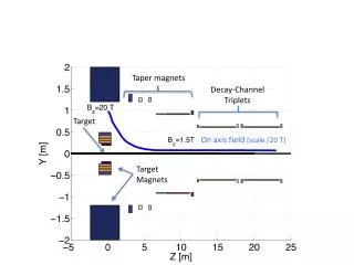
Design by CFD H2 Release/Safety CFD calculations by S. Covrig (Jlab) Heat Exchanger Heater Raster Cell Window GRS Dummy
Design Considerations Knobs to turn: Constraints: Ibeam & Ltgt Window bkg Safety issues Available Pcooling Head ΔAstat Time available ASME compliance • P & T • Vflow • Araster • nhelicity • nraster • Intrinsic φbeam • Cell/Flow design • Window design GRS
Extrapolating Performance Need similar performance to Qweak. Penalty rises rapidly with target noise & with flip rate:
Extrapolating Performance Raster LtgtIbeamMassflownhelicity Qweak = 238 ppm x 0.16 x 7.5 x 2.1 x 0.27x 0.19 = 31ppm Note: G0 achieved σboil = 100ppm with 3x3 mm2 raster. G0 achieved σboil = 68 ppm with 2* the pump head. Dependence on G0 target massflow was cubic! Here we take it to be linear (ultra-conservative). Linear: 0.27 ( 31ppm) Quadratic: 0.071 ( 8 ppm) Cubic: 0.020 ( 2 ppm!!!) This dependence determined empirically from a single test which mimicked nhelicityflipping using gate widths, and the Hall C standard pivot tgt. This is a bold extrapolation given how little we still understand it… Not reliable. However, part of the gain is purely statistical. That is reliable! Would like more flexibility here! We know this knob works! Option 7x7 mm2 ? Note: At 2 kHz flip rate, expect ΔA(stats) = 78 ppm. Need σboil ≤ 26 ppm to keep runtime penalty < 10%
Msrd 30 Hz Δρ/ρ in Hall A From Armstrong, Moffit & Suleiman (2004) Machined 15cm LH2 beer can cells Measured in Hall A with lumis Confirms we win with Araster & νfan
G0 Raster & Pump Scaling S. Covrig et al., NIM A551, 218 (2005). 31 Hz pump 42 Hz pump Measured width vs raster size (stats & tgt noise in quadrature)
Higher helicity reversal rates The statistical width is given by: • We can reduce the relative contribution of the target boiling term by going to higher helicity reversal frequencies (increased counting). • Tests (VPI/Jlab/OU, June 2008) with a Hall C standard tgtindicate that the boiling term drops with frequency as: Measured 80 μA 60 μA 40 μA 20 μA GRS
Cryo re-summary • New 4 kW ESR-II • Available 2013 – 2014? • Nominally 4.5 K, 3 atm supply • Return at 2.5 atm (only ½ atmΔP!) • Possibilities for 6 kW at 15 K ? • Old 1.2 kW ESR will survive • Advised to plan for a hybrid HX ala Qweak • Excess CHL capacity a possibility (unofficially)
3 kW Hybrid Heat Exchanger • Cooling Power >3000 W! • Combine capabilities of both 4K and 15K refrigerators hybrid HX • 4 K: 2 layers, 2.4 kW @20 g/s • 15 K: 1 layer, 900W @17g/s • 24 liters of LH2. • CFD: head & freezing. • Head: 0.6 psi @ 1 kg/s • Doesn’t freeze despite 4K coolant • Basic design performance calculated analytically (counterflow HX): 87.3 cm long, 27.3 cm diameter
Loads/Capacities: CHL 6GeV vs.12GeV Color key 6 GeV ops 12 GeV ops Both From a talk by D. Arenius at ILC08, Univ. Illinois, Nov. ‘08
Viscous Heating A2, V2=V1*A2/A1 A1, V1 Flow (Abrupt Enlargement) (Abrupt Contraction, Commercial Fittings) (Circular Pipe) Ex: 15 l/s, 2 psi, 80% 250 W 30 l/s 2000 W! Note: ΔP = hLρ g, Re = v d ρ / μ, e ~ 0.0015 mm for Al pipes
Cooling Power Requirements Pb=4.5 kW! Pb(W) = Ib(μA) (g/cm3) t(cm) dE/dx(MeV/g/cm2) With: Ib=85 μA, ρ=0.072 g/cm3, t=150 cm, Cooling Power Budget Coolant Massflows for a 20K tgt 13K Mass Flow (g/s) 15K 4K Cooling Power (W)
5 kW He ΔP with existing Infrastructure LN2 Supply: Inner pipe 5” IPS Outer pipe 6” IPS Both Sch-10 A=7.4 in2 Transfer Line Anatomy 15 & 20 K: ¾” IPS pipe, Sch-10 0.884” id, A=0.6 in2 Return: 1 ¼” IPS pipe, Sch5 = 1.66” od, .065” wall, A=1.8 in2 Supply: Annular space inside 2” od tube, .065” wall, A=0.6 in2
ODH • Last time relayed a potential ODH concern • Because of addt’l coolant flow • However: • Hall engineer (Brindza) says Helium was never an ODH concern no restrictive orifice • Cuz it rises, escapes hall thru dome vent • ODH concern is on LN2 supply- it has a restrictive orifice • But we will not use the LN2 supply (as a LN2 supply) • No ODH issue here. But may be a flow restriction.
Cryo Caveats: • Both HRS’s (& septa) at 300K • No LN2 usage (supply line hijacked) • SC Moller solenoid a special problem • Was a challenge to solve for Qweak • Minimal loads from the other halls • MOLLER will require ~all of the coolant • This problem is scheme-dependent • Some schemes impact other halls less • No (low) losses in xfer lines • Stay flexible. Meet with cryo early
E158 Liquid Hydrogen Target Refrigeration Capacity 1000W Max. Heat Load: - Beam 500W - Heat Leaks 200W - Pumping 100W Length 1.5 m Radiation Lengths 0.18 Volume 47 liters Flow Rate 5 m/s Disk 1 Disk 2 Disk 3 Disk 4 Wire mesh disks in target cell region to introduce turbulence at 2mm scale and a transverse velocity component. Total of 8 disks in target region.
Prototype for 11 GeV Møller Target Cell Beam heating 4600 W @85 μA Need δρ/ρ < 26 ppm @ 2000 Hz Predicted ΔP = 0.5 psid CFD by S. Covrig, JLab Beam 150 cm Prototype: E158-type Target Cell 150 cm long, 3” diameter Shows obvious areas where improvements can be implemented. CFD: Disks do not seem to help!
Bulk Heating • First CFD model has clear problems at flow inlet. Still: • ΔT(global) = 0.4 K • ΔT(beam volume) = 1.2 K • Δρ/ρ = 2% • Clearly due to hot spot in the model • ΔT = Q/(m CP) = 0.4 K (best you can do) • Not an onerous situation
Film Boiling @ Windows Total Heat Flux (dE/dx) / Araster • MOLLER looks promising: careful design may eliminate film boiling @ windows! Threshold for film boiling Convective part Predicted by CFD
Two Phase CFD (window boiling) CFD simulation by S. Covrig Rastered Beam profile on 0.005” Al cell entrance window Entrance Window Velocity Contours Both Phases LH2 Flow Vapor Only (BLUE means no vapor there, ie just liquid).
Qweak Lessons • ASME compliance has been a nightmare • Should be less onerous for Moller. • Biggest problem: lack of management support for early testing • This will not change. Priority goes to “next experiment”, & polarized targets. • Only solution I see is to build offsite, then test here (ala G0). • We can build on-site. But then forget early testing. • ASME complicates this, but it’s still possible • Hold initial design review early
ASME Qweak target design authority: D. Meekins
Target Cooling Power Loads • Beam: Pb(W) = Ib(μA) (g/cm3) t(cm) dE/dx(MeV/g/cm2) • With: Ib=85 μA, ρ=0.072 g/cm3, t=150 cm, Pb = 4.5 kW! • Viscous Heating: Pv(W) = 6.89 Flow(l/s) Head(psi) / ε • With: Flow 15 l/s, Head 1.3 psi, ε=60%PV = 225 W • PID Loop (feedback): need heater power to control T • Reserve ~ 150 W • Pump heat: Pp (W) ~ 20% (Pump power (hp) * 745.7) • With: pump power = 0.5 hp, Ppump ~ 75 W • Conductive losses: • Guess, 50 W
2004 Cryo Agreement Confirmed during spring, ‘09 tests: See TN-09-041
Closest Comparison: Qweak • Still virtual, but many lessons learned • Novel, dual HX technique & design approved • Use large Araster & vflow (viscous heating limit) • Cryo-agreement negotiated fall 2004 • thru JROC: all ADs, cryo, tgts, Qweak • Coolant supply methods identified • High pressure loop higher T, more cooling power, more sub-cooling • CFD calculations steering cell design • Fast (~300 Hz) helicity reversal
Pmax Considerations Lower P: Higher P: More cavitation headroom = Pop – PVP . Cavitation occurs at trailing edge of pump blades when P < PVP . For LH2 PVP(19K) ~ 10 psia. Higher boiling temps Run at higher T more cooling power Run at fixed T more subcooling Less film boiling at windows? No (App. 9.1) • Don’t go sub-atmospheric • Thinner windows = less bkg • Lower warm gas storage P • Less gas inventory GRS Settled on 35 psia & 20 K
Comparisons Moller • 2.4 times Qweak • 17 times G0 forward • 20 times E158
Energy Loss (11 GeV, 150 cm LH2) • Ionization Energy Loss • 4.995 MeV/g/cm2 • ~10% Higher than at lower energies • 54 MeV total (what counts for heat load) • Bremsstrahlung Energy Loss • 1.74 GeV ! total • That’s 16%! Forget your focus!
The G0 Target Loop CFD calculation by S. Covrig, UNH