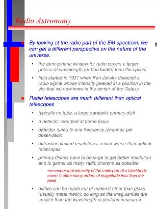
Download
1 / 77
780 likes | 1.01k Views
ATP-NSI. Cross- correlators for Radio Astronomy. Brent Carlson, NRAO Synthesis Imaging Summer School. 29 May 2012. Outline. What is the purpose of the correlator? Simplified signal flow Basic correlator architectures XF, FX, hybrid Technology How do the electronics “work”

E N D
ATP-NSI Cross-correlators for Radio Astronomy Brent Carlson, NRAO Synthesis Imaging Summer School 29 May 2012
Outline • What is the purpose of the correlator? • Simplified signal flow • Basic correlator architectures • XF, FX, hybrid • Technology • How do the electronics “work” • The development process • JVLA WIDAR correlator • Now and the future
Purpose • To calculate the integrated cross-power response for each pair of antennas “X” and “Y” in the array over some integration time “T”.
Purpose • The outputs of the correlator are the visibilities—spatial Fourier components—for each baseline B in the u-v plane that are used to build the image. • The fun begins: • As number of antennas and bandwidth increases. Number of baselines is ~N2/2. Bandwidth means higher performance (speed) electronics.
Purpose • The analog signal is quantized—in time and amplitude—as soon as possible for stability and to take advantage of “cheap” high-speed digital electronics. • Once the signal is “digitized” there are no more unknown/unquantifiable effects (well, unless something broke…)
Simplified signal flow • STEP #1: • Receive and amplify the signal from the antenna.
Simplified signal flow • What does the signal “look” like? • Time domain (analog):
Simplified signal flow • STEP #2: • down-convert (mix) and filter the signal…ready for digital sampling.
Simplified signal flow • STEP #3: • quantize (digitize/sample) the signal.
Simplified signal flow • What does the signal look like? • Time domain (digital):
Simplified signal flow • Sampling: • Nyquist sampling theorem: must sample at least 2X the signal bandwidth to obtain all information about the signal. If less, leads to “aliasing” (confusion). • With noise input: • 2-bit: 12% sensitivity loss. • 3-bit: 3.5% sensitivity loss—JVLA wideband samplers • 4-bit: 1.5% sensitivity loss—JVLA correlator “internal samplers”
Simplified signal flow • Sampling: • adding more bits/sample produces diminishing sensitivity returns for noise input and integrated output. • When narrowband interference is present, need more bits so as not to contaminate the spectrum with saturated sampler-generated harmonics. Get ~6 dB per bit dynamic range for a pure tone. dB=10log(x); if x is a power value. • For real-time signals (music/video) need lots of bits to accurately represent the real-time waveform (e.g. CD ~16-bit sampling=216 = 65,536 levels)
Simplified signal flow • STEP #4: • Correct for antenna-dependent wavefront delay. • Two steps: • Pure digital delay to +/-0.5 samplesusing memory. Get up to +/-90 deg phase changes at the upper edge of the band…severe decorrelation, therefore need: • Sub-sample delay to << +/- 0.5 samples. Various methods, sometimes analog, often digital… JVLA WIDAR uses a digital method.
Simplified signal flow • STEP #5: • Cross-correlate and accumulate. • Must also correct for “fringe phase” due to the fact that wavefront delay compensation occurs at a different frequency (baseband) than where it originally occurred (at RF in free space). • Various correlator methods to be discussed later…
Simplified signal flow • What does the signal look like? • Frequency domain (10e6 samples integrated):
Correlator architectures • There are two basic methods for correlation: • “XF”: Cross-correlate in the time (tau) domain, then Fourier transform (after integration) to the frequency domain. a.k.a. “lag correlator” • “FX”: Fourier transform in the (real) time domain, then multiply and integrate in the frequency domain. “Convolution in one domain is multiplication in the other domain”
Correlator architectures • Hybrid: • Combination of the two. JVLA WIDAR does this as does the ALMA correlator. • Coarse filter into sub-bands (F), XF each sub-band. • More details later.
Correlator architectures • XF: • traditionally simpler to understand+implement—especially for 1-bit or 2-bit correlators (e.g. 1-bit correlator multiplier is XOR gate). Important in “earlier days” because of speed and logic availability. • O(Nchan x sample rate) multiplies/sec…but, very simple operations (multiply-accumulate) on few bits.
Correlator architectures • FX: • More complex, many-bit operations (FFT). (Has been) more difficult to implement/understand. • O(log Nchan) x sample rate multiplies/sec…much more efficient…in principle. • Problems: • Have word-width expansion after FFT: (has been) 1 or 2-bit in, many bits out. • How to window the real-time data before FFT?
Correlator architectures • See: • Harris, Dick, Rice, “Digital Receivers and Transmitters using PolyphaseFilterbanksfor Wireless Communications”, IEEE transactions on microwave theory and techniques, Vol. 51, No. 4, April 2003. • …for more detail on poly-phase filterbanks(great paper!)
Correlator architectures • Hybrid F-XF • 1st stage: coarse filterbank. • Useful as “digital BBC” for frequency-agile sub-band placement. • 2nd stage: XF. • Attractive as an simple+efficientparallel processing method for wideband signals since no large multiplier operations are required (all ops with memory and adders). • JVLA and ALMA correlators built this way (some slight differences in implementations). Probably the last of this breed!
Correlator architectures • The actual signal processing operations are just one piece of the puzzle when putting a system together. • Much of the logic and power in a system is consumed by transporting data around, synchronizing, providing various modes of operation, error detection and recovery etc. • Let’s look “under the hood” of the electronics…
Technology • It all starts with fundamental physics…but moving up a level or two: • Transistor “switch”: the FET – Field Effect Transistor.
Technology • N-MOS: applying a voltage to the Gate opens a conduction channel between the Drain and Source. • P-MOS: applying a voltage to the Gate closes the conduction channel between the Source and the Drain.
MOS: Metal Oxide Semi-conductor. MO is the insulator between the gate and the conduction channel. Extremely sensitive to electro-static discharge (ESD). When the transistor is ON or OFF, no current flows from the gate to the conduction channel (unless it is blown…) Current (power) only flows when changing states, to charge/discharge the gate capacitance…faster state changes consumes more power.
CMOS: Complementary Metal Oxide Semiconductor. Output changes faster since it is being driven both high and low. Small amount of leakage current (power) when the conduction channel is switching states.
F.A. (Full Adder) A 4-bit 2’s complement multiplier: 16.7 million of these in JVLA WIDAR correlator.
Technology • A logic gate “immediately” reflects changes on its input to its output. It can’t store a value. • A “Flip-Flop” transfers “Data in” to the output “Data out” only on the edge of its clock: A Flip-flop can therefore store a value…a single bit.
Technology • In digital electronics, pretty much everything is “synchronous”. i.e. changes occur on the clock edge all “in step”. • It’s like a production line… the speed of the line is the clock speed and in each clock cycle each “worker” (bunch of gates doing some logic function) must get their step done before the next clock cycle starts. • As the clock speed increases, the logic “workers” must go faster to keep up.
Technology • Together (and in the millions/billions), Flip-flops and gates (along with memory cells) form the bulk of all digital electronics. • As “feature sizes” (transistors) get smaller, more gates can be packed on a chip, they run faster, and more can be done. • JVLA correlator implemented with 90 nm and 130 nm devices (c. 2005). • Industry currently shipping 28 nm devices…20 nm is next…
Development process • In logic design, at the “application level”, we don’t (or, rarely) design explicitly with gates and flip-flops. • We write HDL – Hardware Description Language code that describes logic in a high-level fashion. • And there are higher-level approaches as well… • Can (optionally) use hierarchical graphical design tools as well to improve the human’s ability to understand how it all fits together.
JVLA WIDAR correlator • 32 antennas, 8 GHz/polarization (in 2 GHz chunks 3-bit sampling; alternately 4 x 1 GHz 8-bit sampling). • 128 independently tunable digital sub-bands; 128 MHz, 64 MHz, …,31.25 kHz BW per sub-band.
JVLA WIDAR correlator • Each sub-band can have a different delay center on the sky, within the antenna primary beam. • 16,384 to 4 million spectral channels per baseline…