Download
1 / 24
320 likes | 792 Views
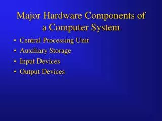
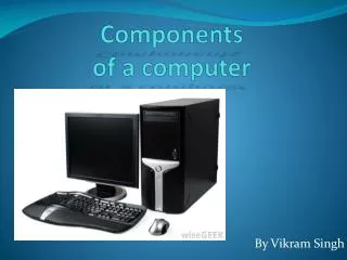
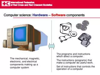
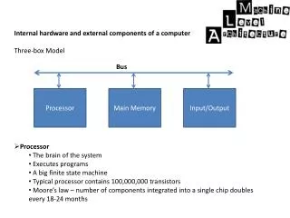
Internal hardware and external components of a computer Three-box Model Processor The brain of the system Executes programs A big finite state machine Typical processor contains 100,000,000 transistors

E N D
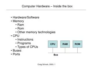
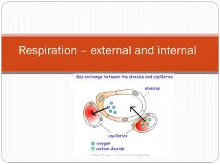
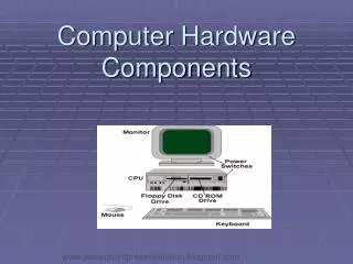
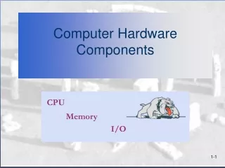
Internal hardware and external components of a computer • Three-box Model • Processor • The brain of the system • Executes programs • A big finite state machine • Typical processor contains 100,000,000 transistors • Moore’s law – number of components integrated into a single chip doubles every 18-24 months Bus Processor Main Memory Input/Output
Internal hardware and external components of a computer • Main Memory • Also known as ROM, RAM or IAS (Immediate access store) • Mainly used to store program instructions and data • Available in memory chips able to store 512k. • Integrated onto bigger boards to store up to 4gig in 32bit computers • ROM – Read only memory • RAM – Random Access Memory • EEPROM – Electrically erasable programmable read only memory • Bus • The three areas are connected by a set of parallel wires • These wires pass signals between the components. • There are 3 types of bus • Data – a bidirectional bus, typically consisting of 32 wires used to transport data between components • Address – a unidirectional bus, typically consisting of 32 wires used to address memory and I/O locations. • Control – a bidirectional bus, typically consisting of 8 wires , used to transport control signals between the components.
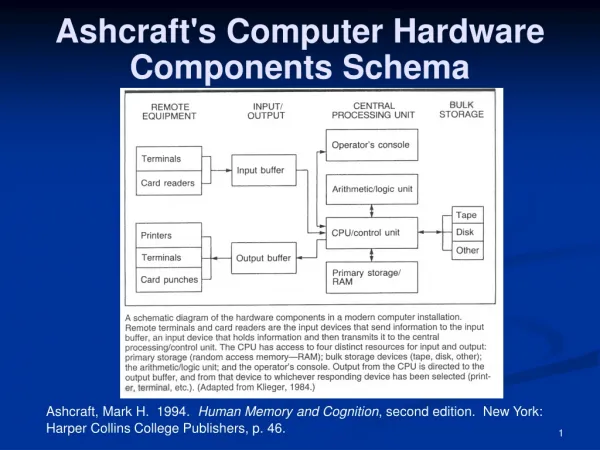
Internal hardware and external components of a computer • Input / Output (I/O) • Commonly known as peripherals. Processor Control Bus Main memory Data and Address Buses Keyboard Input Controller VDU Output Controller Keyboard Visual Display Unit (Disk) I/O Controller Secondary Store
Internal hardware and external components of a computer • Peripherals • A computer device that is not part of the CPU. • The system bus is not connected directly to I/O devices but via an I/O controller • The I/O controller is connected to the I/O device • I/O Controller • The controller is an electronic circuit consisting of three parts • Electronics that interface the controller to the system bus • A set of data, command and status registers • Electronics appropriate for sending control signals to the device connected to the computer • Secondary Storage • This is a permanent storage memory that is a peripheral to the CPU e.g. A hard disk.
Functional Characteristics of a processor. • A processor controls the system bus • Performs operations on data by executing program instructions • Program instructions are stored in main memory and are “Fetched” by the Processor • Only one operation can be carried out at one time for each processor. • A large part of the traffic on the system bus is addresses for memory locations. • Addressable Memory • Memory locations each have a unique address which the processor sends down the address bus. • The processor determines over the control bus whether it needs to read or write to that memory location. • The processor uses the data bus to then transfer any data back and fore.
Functional Characteristics of a processor. • Stored program concept • Proposed by John von Neumann and Alan Turing • A program must be resident in main memory to be executed • machine code instructions are fetched, one after another, from main memory in sequence and are executed, one at a time in the processor. • Von Neumann stored program computer • A serial machine • Instructions are fetched one after anaother • Single memory shared between program instructions and data. • Data and instructions travel along a shared data bus. • Harvard stored program computer • Separate instruction and data memories • Separate instruction and data buses • Still functions as a serial computer • Harvard Vs Von Neumann • No sharing resources with accessing data and instructions so the performance speed of a Harvard infrastructure is better.
Functional Characteristics of a processor. • Microcontroller • A complete computer on a single chip. Processor, memory and I/O • Used for small devices where a cheap compact system is required, e.g. Mp3 players • Often use the Harvard architecture.
Functional Characteristics of a processor. Structure and role of the processor A processor consists of the following components Program Control Unit Fetches program instructions from memory, decodes them and executes them one a time 2) Arithmetic Logic Unit The ALU performs arithmetic and logical operations on data such as addition and subtraction, fixed point and floating point arithmetic, Boolean logic such as AND, OR< XOR and a range of shift operations. 3) Registers Fast memory locations inside the processor that may be dedicated or general-purpose 4) Internal Clock Derived directly or indirectly from the system clock
Functional Characteristics of a processor. Structure and role of the processor A processor consists of the following components 5) Internal Buses Several internal buses link the control unit, the ALU and the registers 6) Logic gates Used for flow control
Functional Characteristics of a processor. • General Purpose and dedicated registers • General Purpose • Fast memory locations used to store data temporarily • Labelled as R1, R2.....Rn • Accessed with instructions such as LOAD, STORE and ADD • Dedicated Registers • Stack Pointer (SP) • Points to a stack holding return addresses, procedure or functional parameters, and local variables. It is accessed when a procedure or function is called or an interrupt is serviced. • 2) Program Counter (PC) • Points to the next instruction to be fetched and executed
Functional Characteristics of a processor. General Purpose and dedicated registers Dedicated Registers 3) Status Register Holds condition codes to indicate the outcome of operations e.g. Positive, negative, zero, interrupts enabled or overflow. 4) Accumulator (ACC) The result of the current set of calculations 5) Current Instruction register (CIR)Holds the current instruction to be executed while it is decoded and executed 6) Memory Address Register (MAR) Holds the address of the memory location currently being accessed by the processor. 7) Memory Buffer Register (MBR) Holds the data item being transferred to or from the memory location currently being accessed by the processor. Sometimes called the MDR (Memory Data Register)
Functional Characteristics of a processor. • System Clock and Clock Speed • Timing signals that are used to regulate the rate at which instructions are executed • Used to synchronise the operation of various computer components. • Measured in megahertz (MHz) or gigahertz (GHz) • This frequency is known as clock speed. • Instructions required a set amount of clock ticks to execute. • The frequency of these ticks can be increased by frequency multiplying circuits to the rate that is required by the processor. • Clock ticks are provide to regulate the transfer of data, addressed and control signals along the busses at a slower rate than the processor. • Clock speeds double every year. • Intel 8088 (1990 – 4.77MHz) • 486 DX2 66 – 66Mhz (1994 est) • Pentium – Up to 300 Mhz • Pentium 4 up to 3-4 GHz • Dual Core – Up to 6GHz • Quad Core
Functional Characteristics of a processor. • Limits on Clock Speed • A limit needs to be set on clock speed due to the heat being generated by the chip with higher frequencies. This is why modern computers have a fan directly on the chip itself. • This causes a deviation from Moore’s law due to the level of heat and power consumption. • To solve this problem multiple cores are now used with lower frequencies. • Multicore Processors • More processors are put onto one microprocessor chip. • These processors are called cores • Operate at lower frequencies • Multiple tasks can be implemented and processes can be split.
Functional Characteristics of a processor. Word Length Computers works with binary words which are codes for instructions, memory addresses, characters, integer numbers, colours of pixels and digitised sound samples. The greater the word length the greater the instruction set, the larger the memory, the larger the numbers that can be used etc.. Increasing Word length Increasing this allows larger operands in instructions preventing the need to spend time breaking down the operands which affects performance. 32 bit computers can have more memory than 16 bits computer as more addresses accessable. Bus Width The number of wires on a bus. Each wire represent one bit of information. This affects the word length. Increasing the bus width will obviously affect the performance as more data and larger addresses can be accessed.
CPU WARS Episode 1 A day in the life of a CPU Fetch Decode Execute Cycle
The Program Counter The Players The Control Unit The Memory Data Register (MDR) The Clock The Memory Address Register (MAR) The Status Register The Current Instruction Register (CIR) The Arithmetic Logic Unit (ALU) The Accumulator The Interrupt Register
Scene 1 – The Fetch Hi PC. What is my next instruction? Hi CU. This is your next instruction and where in Memory you can find it.
Since this is an address the MAR needs to hold its location. F124 AC4D
Scene 1 – The Fetch Address bus – I need you to go to the memory with this address for my next instruction No problem sir! Ah . This is the instruction from the Memory
Scene 1 – The Fetch There you go sir. Thankyou CIR Right. I can now increment to the next instruction I now need to pass this instruction onto the CIR 0110100101
Instruction Set 0000101010 – Add 0110100101 – Move 0010101010 – Subtract 1110101100 – Multiply 1100000111 - Store Scene 2 – The Decode Right. I have my instructions – now what do they mean? I better check my instruction set. Ah cool. According to this my instruction is “MOVE”
Scene 3 – The Execute Ok Guys. Thanks for all of you coming. Here is what I would like you to do…..
The End…. Tick..