Download
1 / 14
160 likes | 356 Views
RF fiber optics. Analog RF transmission with mechanically stressed fibers. Introduction. Advantages of fiber links: Bandwidth depends mainly on the electrical components Very long distances can be achieved Current installation in the Effelsberg telescope:

E N D
RF fiber optics Analog RF transmission with mechanically stressed fibers
Introduction • Advantages of fiber links: • Bandwidth depends mainly on the electrical components • Very long distances can be achieved • Current installation in the Effelsberg telescope: • 400m from primary focus cabin to faraday room • Transmission of RF signals through coaxial cables (25 dB/100m @ 1GHz) • Max. useable bandwidth < 1 GHz • Analog transmission is able to avoid the bandwidth bottleneck
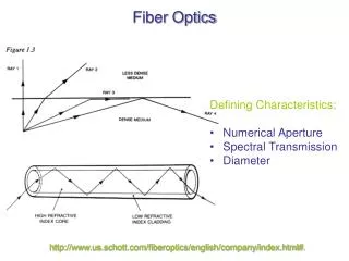
Analog fiber links • Miteq SCM Series 0.1 – 18 GHz • Miteq MDD Series 0.1 – 11 GHz • 9/125 single mode fiber with FC/APC connectors • Laser is modulated directly
Results of broadband meas • TP_in: nearly constant • TP_out: -0,47 – 0,25 dB
VNA Measurements • Build up at the lab bench • No loop • Miteq SCM Transmitter (18 GHz BW) • Miteq SCM Receiver (18 GHz BW) • Miteq MDD Transmitter (11 GHz BW) • Miteq MDD Receiver (11 GHz BW) • 100m 9/125 SM fiber • 2m 9/125 SM fiber
Summary • MDD (11 GHz) Receiver: ∆A = 0.22 dB • SCC (18 GHz) Receiver: ∆A = 0.78 dB • Transmitter has no influence • Same measurements with 2m fiber instead of 100m:no change Fiber length has no influence • Measurments with the fiber installed in the telescope are compareable with those in the lab although the fiber is different Fiber type has no influence
Conclusion • Changes in insertion loss:Effect seems to depend on birefrigence caused by mechanical force applied to the fiber. Together with a polarization sensitivity of the photodiode this can cause the difference in insertion loss. • Changes in frequency response:Still an open question; Has to be investigated further