Download

1 / 23
250 likes | 704 Views
Fiber Optics. FIBER MANUFACTURING. Fiber Optics. Now that we know how fiber-optic systems work and why they are useful -- how do they make them? Optical fibers are made of extremely pure optical glass.

E N D
Fiber Optics FIBER MANUFACTURING
Fiber Optics • Now that we know how fiber-optic systems work and why they are useful -- how do they make them? Optical fibers are made of extremely pure optical glass. • We think of a glass window as transparent, but the thicker the glass gets, the less transparent it becomes due to impurities in the glass.
Fiber Optics • However, the glass in an optical fiber has far fewer impurities than window-pane glass, it is 99.9% pure. • One company's description of the quality of glass is as follows: If you were on top of an ocean that is miles of solid core optical fiber glass, you could see the bottom clearly.
Fiber Optics • Three methods are used to fabricate low loss waveguide fibers: MCVD: Modified chemical vapor deposition OVD: Outside vapor deposition VAD: Vapor axial deposition
Fiber Optics • Making optical fibers requires the following steps: • Making a preform glass cylinder • Drawing the fibers from the preform • Testing the fibers
Fiber Optics • The (MCVD) Modified chemical vapor deposition preforms are made by oxygen bubbled through solutions of silicon chloride (SiCl4), germanium chloride (GeCl4) and/or other chemicals.
Fiber Optics • The precise mixture governs the various physical and optical properties (index of refraction, coefficient of expansion, melting point, etc.). • The gas vapors are then conducted to the inside of a synthetic silica or quartz tube (cladding).
Fiber Optics • A hollow glass tube 3 feet long and 1 inch in diameter is placed in a horizontal lathe and spun rapidly,as the lathe turns, a torch is moved up and down the outside of the tube.
Fiber Optics • Each pass of the heat source fuses a small amount of the precipitated gas mixture to the surface of the tube. • Most of the gas is vaporized silicon dioxide (glass), but there are carefully controlled amounts of dopants (impurities) that cause changes in the index of refraction of the glass. • The dopant mixture can be changed for each layer to vary each index of refraction.
Fiber Optics • After sufficient layers are built up the tube is collapsed into a solid glass rod referred to as the preform.
Fiber Optics • The OVD (outside vapor deposition) method utilizes a glass target rod that is placed in a chamber and sun rapidly on a lathe. • A computer controlled mixture of gases is then passed between the target rod and the heat source.
Fiber Optics • On each pass of the heat source, a small amount of the gas reacts and fuses to the outer surface of the rod. • After enough layers are built up, the target rod is removed and the remaining soot preform is collapsed into a solid rod. • The preform is then taken to a tower and pulled into fiber.
Fiber Optics • The VAD (vapor axial deposition) process utilizes a very short glass target rod suspended by one end. • A computer controlled mixture of gases is applied between the end of the rod and the heat source.
Fiber Optics • The heat source is slowly backed off as the preform lengthens due to tile soot buildup caused by gases reacting to the heat and fusing to the end of the rod. • After sufficient length is formed, the target rod is removed from the end, leaving the soot preform. • The preform is then taken to the drawing tower to be heated and pulled into the required fiber length.
Fiber Optics • The fiber drawing tower.
Fiber Optics • The blank gets lowered into a graphite furnace (3,452 to 3,992 degrees Fahrenheit or 1,900 to 2,200 degrees Celsius) and the tip gets melted until a molten glob falls down by gravity. • As it drops, it cools and forms a thread.
Fiber Optics • The firing process in the draw tower.
Fiber Optics • The operator threads the strand through a series of coating cups (buffer coatings) and ultraviolet light curing ovens onto a tractor-controlled spool.
Fiber Optics • The tractor mechanism slowly pulls the fiber from the heated preform blank and is precisely controlled by using a laser micrometer to measure the diameter of the fiber and feed the information back to the tractor mechanism.
Fiber Optics • Fibers are pulled from the blank at a rate of 33 to 66 ft/s (10 to 20 m/s) and the finished product is wound onto the spool. • It is not uncommon for spools to contain more than 1.4 miles (2.2 km) of optical fiber.
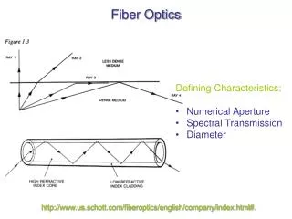
Fiber Optics • Tensile strength - Must withstand 100,000 lb/in2 or more. • Refractive index profile - Determine numerical aperture as well as screen for optical defects. • Fiber geometry - Core diameter, cladding dimensions and coating diameter are uniform.
Fiber Optics • Attenuation - Determine the extent that light signals of various wavelengths degrade over distance. • Information carrying capacity (bandwidth) - Number of signals that can be carried at one time (multi-mode fibers). • Chromatic dispersion - Spread of various wavelengths of light through the core (important for bandwidth).
Fiber Optics • Operating temperature/humidity range. • Temperature dependence of attenuation. • Ability to conduct light underwater - Important for undersea cables.