Download

1 / 20
220 likes | 453 Views
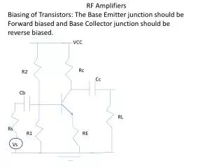
LAAS-CNRS Toulouse, France. IEEE Topical Workshop on Power Amplifiers for Wireless Communications September 9 and 10, 2002 San Diego, CA . Practical Implementation of Adaptation in a Digital Predistorter for RF Power Amplifiers. A. Cesari , D.Dragomirescu, P. Lacroix, J.M. Dilhac. LNA.

E N D
LAAS-CNRSToulouse, France IEEE Topical Workshop on Power Amplifiers for Wireless Communications September 9 and 10, 2002 San Diego, CA Practical Implementation of Adaptation in a Digital Predistorter for RF Power Amplifiers A. Cesari, D.Dragomirescu, P. Lacroix, J.M. Dilhac
LNA PA 3 - Compression and warping 4 - Increased BER NEEDFOR LINEARITY! 1 - Out of band emission 2 - Energy loss INTRODUCTIONNon Linearity of the Power Amplifier LPF I Q 16-QAM signal
POWER AMPLIFIER INTRODUCTIONNon Linearity of the Power Amplifier LINEARISATION MECHANISM Analog/Digital Adaptative or not Baseband/RFBand
Digital: use of DSP chips Low cost Low power consumption Small size NEWER APPROACH LINEARISATION STRATEGIESDigital & Adaptative Adaptative: a feedback path exists • Generic approach • Intended for low development time • Ability for self training • Ability to account for changes in the system and consequent adaptation DEALING WITH FEEDBACK BETTER PERFORMANCES
y z x x c y c z c O + * * fPD(x) gPA(y) * * fPD gPA + PA Out Good z wrong z gPA(.) x PA In y LINEARISATION STRATEGIESGeneral Predistortion Strategy Output signal Forward signal Desired, linear characteristic
x = (xI, xQ) = |x|ej * + y = (yI, yQ) = |y|ej fPD? x C y C Look-Up Table: fPD x + = y MAPPING x = y yQ COMPLEX GAIN + xQ * POLAR |x|Gej+ = y |y| |x| Polynomial: Complex plane C1·x + C2·x 2 + C3·x 3 … = y xI yI LINEARISATION STRATEGIESGeneral Predistortion Strategy Well known techniques or or or
adaptation comparison LINEARISATION STRATEGIES Adaptive Digital predistortion • Aging, temperature drifts • Changes in work frequency • Part to part variation, load mismatch • Need for perfect synchronisation • Tradeoffs: Bandwidth, fsample, complexity x z y fPD(x) gPA(y) * O + adaptation comparison Feedback signal
COMPARISON & ADAPTATIONSample-by-Sample basis FORWARD signal x adaptation Calculate fPD(x,z,e) error signal comparison + - z FEEDBACK signal
PA adaptation comparison Delay estimate COMPARISON & ADAPTATIONOverview of Delays delay fsx fsx xi,xq yi,yq Mod Nyquist filter PD DAC zi,zq DeMod ADC FIFO fsz delay = kTsz + k = 0,1,2,… < Tsz/2 After digital delay estimation Residual delay =
COMPARISON & ADAPTATIONExample Worst case delay, = Tsz/2 FORWARD signal error FEEDBACK signal
COMPARISON & ADAPTATIONParameters of Interest • 1 . Fsx: sampling rate at FWD path, digital stage • As high as possible, BW of PreDistortion • 2 . Fsz: sampling rate at feedback path, digital stage • As high as possible, accuracy of delay error • 3 . SSx: samples/symbol at Tx, digital stage • As high as possible; accuracy of delay error • But if SSx’s up, Fsx needs to be incremented • by the same amount in order to maintain BW!
COMPARISON & ADAPTATIONOur proposal: Multirate DSP • Keep Fsx as high as possible • Keep SSx as low as possible (i.e. IS-95, SSx = 4) • Increment Fsz: oversampling Feedback signal FWD signal fsz = 2fsx amplitude amplitude samples samples
COMPARISON & ADAPTATIONMultirate DSP Objective: Study the impact of oversampling & multirate DSP over the delay error magnitude • Experience 1: measure of the (worst case) delay error • along the Dynamic Range of a QAM signal • Experience 2: improvements after oversampling
COMPARISON & ADAPTATIONExperience 1 Measure of the (worst case) delay error along the Dynamic Range of a 16-QAM signal Px - Pz Delay = kTsz + x ? Delay = =Tsz/2 Px FORWARD signal digital @ fsx = fsz @ fsz z comparison + - Digital Delay adjust FEEDBACK signal Worst Case sampling rms2 rms2 analogic Px Pz
0,15 COMPARISON & ADAPTATIONExperience 1 fsx = fsz = 4 SSx fsx = fsz = 16 SSx Px - Pz Px - Pz Px Px
COMPARISON & ADAPTATIONExperience 2 Oversampling & Multirate: • Keep the samples/symbol ratio at minimum • fsz > fsx at ADC & DAC stages Technique 2A: drop samples from the higher rate source (Z) to match the samples of X Technique 2B: true multirate, smoothing through average calculation in the domain of Z
COMPARISON & ADAPTATIONExperience 2 Technique 2A: drop samples from the higher rate source (Z-feedback signal) to match the samples of X-forward signal It results in exactly the same (poor) improvement obtained by increasing both fsx and fsz. Why? fsz sets the limit =Tsz/2 in spite of Tsx
COMPARISON & ADAPTATIONExperience 1 Technique 2B: average filtering (by convolution) in the domain of the oversampled signal, then matching with the signal X-FWD signal Px - Pz Delay = kTsz + x ? Delay = =Tsz/2 Px FORWARD signal digital @ fsx < fsz @ fsz comparison z Digital Delay Adjust & DROP + - FEEDBACK signal Worst Case sampling Avg. filter rms2 rms2 analogic Px Pz
Oversampling x 2, 4 SSx fsx = fsz = 16 SSx Px - Pz Px COMPARISON & ADAPTATIONExperience 2 Oversampling x 2, 4 SSx Px - Pz Px
CONCLUSIONS & FUTURE WORK Adaptive digital predistortion Feedback synchronisation problem Analog delay Traditional solution : high rate samples/symbol Drawbacks : decreased transmission bandwidth incompatibility with 3rd generation wireless telecommunication standards Our proposal : oversampling, multirate, + average filter Future work : physical implementation on a DSP system