Download
1 / 57
770 likes | 1.29k Views
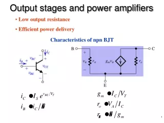
Power Amplifiers. Power Amplifier. Definitions. In small-signal amplifiers the main factors are: • Amplification • Linearity • Gain Since large-signal, or power, amplifiers handle relatively large voltage signals and current levels, the main factors are: • Efficiency

E N D
Definitions In small-signal amplifiers the main factors are: • Amplification • Linearity • Gain Since large-signal, or power, amplifiers handle relatively large voltage signals and current levels, the main factors are: • Efficiency • Maximum power capability • Impedance matching to the output device
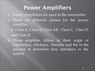
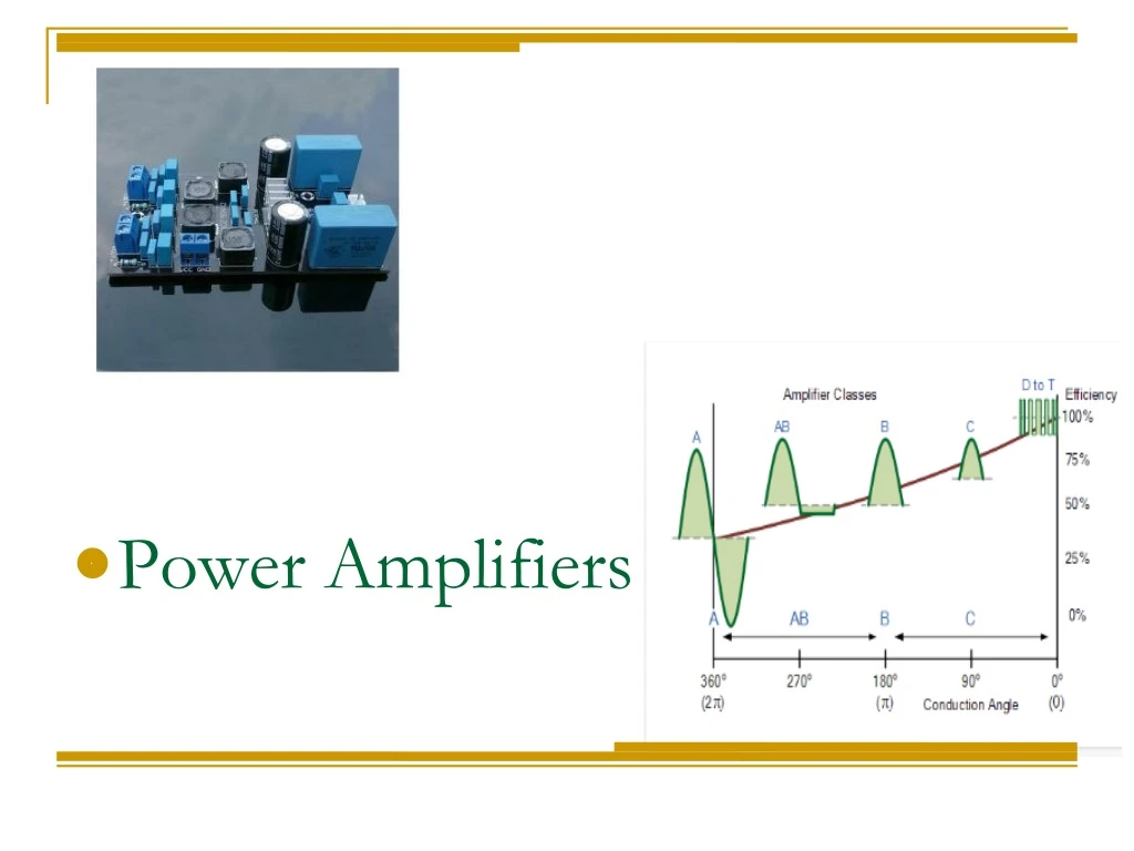
Power Amplifiers • The power amplifiers are classified according to the output signal waveform varies over one cylce of operation for a full cycle of input signal • Types of Power Amplifiers • Class A Power Amplifiers • Class B Power Amplifiers • Class AB Power Amplifiers • Class C Power Amplifiers • Class D Power Amplifiers
Power Amplifier Types Class A The amplifier conducts through the full 360ο of the input. The output signal varies over one cycle of operation for one complete cycle of input signal. The Q-point is set or biased near the middle of the load line. So that at least half output signal swing may vary up and down without going to saturation or cut-off level Its power efficiency is about 25% to 50% Class B The amplifier conducts through 180ο of the input. The output signal varying over only one half of the input signal. The Q-point is set or biased at the cut-off point. Its power efficiency is about 78.5%
Class AB This is a compromise between the class A and B amplifiers. The amplifier conducts or output signal swing occurs between somewhere between 180ο and 360ο. The Q-point is located at a dc level above the zero IB of class B and above one half the VCC level of Class A ie. In between the mid-point and cut-off. Its power efficiency is about 50% to 78.5% Class C The amplifier conducts less than 180 of the input. The Q-point is biased below zero IB i.e is located below the cutoff level. Its power efficiency is about 90% Class D This is an amplifier that is biased especially for digital signals. Its output is like a pulse signal, which is on for short interval and off for a larger interval using digital techniques Power Amplifier Types
Power Amplifier • Performance Quantities of Power Amplifier • The performance quantities or • criteria for a power amplifier are: • Collector Efficiency • Distortion • Power Dissipation Capability
Power Amplifier • Collector Efficiency • The main criterion for a power amplifier is not the power gain but the maximum ac power output. • An amplifier converts dc power from supply into ac power output. • Hence, the effectiveness of a power amplifier is measured in terms of its ability to convert dc power from supply to ac output power. This is called as collector efficiency. • The collector efficiency is defined as the ratio of output power to the zero signal power or dc power supplied by the battery. • collector efficiency Expression
Power Amplifier Expression for collector efficiency Collector efficiency,
Power Amplifier (ii) Distortion The change of output wave shape from the input wave shape of an amplifier is known as distortion. Since , the transistor is a non-linear device, the output is not exactly like the input signal applied to it. Which means distortion occurs.
Power Amplifier (iii) Power Dissipation Capability The ability of a power transistor to dissipate heat is known as power dissipation capability. A power transistor handles large currents and hence, heats up during operation. Since, any temperature change influences the operation of transistor, therefore, the transistor must dissipate this heat to its surroundings. To achieve this, normally a heat sink is attached to a power transistor case. The increased surface area allows heat to escape easily and keeps the case temperature of the transistor within permissible limit.
Power Amplifier (iii) Power Dissipation Capability Diagram represent the power dissipated in the load and transistor • No input signal condition • (PB = 300mW) (ii) Full input signal condition (PB = 300mW) DC power dissipated in load 150mW DC power dissipated in load 150mW Average AC power dissipated in Load 75mW DC power dissipated in the Transistor 150mW 75mW Average power dissipated in Transistor
Class A Power Amplifier In class A power amplifier, the operating point is so adjusted that the collector current flows during the whole cycle of the input signal. The power amplifier circuit is shown in the figure given below shows that the load is connected to the collector through an output transformer. The main purpose of the transformer is to provide perfect impedance matching so that the maximum power is delivered to the load.
Class A Power Amplifier In class A power amplifier, the operating point is so adjusted that the collector current flows during the whole cycle of the input signal. The power amplifier circuit is shown in the figure given below shows that the load is connected to the collector through an output transformer. The main purpose of the transformer is to provide perfect impedance matching so that the maximum power is delivered to the load.
Class A Power Amplifier • (The characteristics of Class A power amplifier ) • The output current flows during the entire cycle of the ac input signal • The operation of the amplifier is limited to smaller central region of the load • line, so that it can operate in the linear region of the load line(It can amplify • small signals) • As transistors operates over the linear region of the load line, The output • waveform is almost similar to the input waveform • The ac power output per active device(transistor) is smaller than that of • Class B or C • The maximum possible overall efficiency of a class A series fed resistive • load is 25%(Very Poor) and for transformer coupled load it may increases to • 50%
Class A Power Amplifier • The advantages of Class A power amplifier are as follows − • The current flows for complete input cycle • It can amplify small signals • The output is same as input • No distortion is present • The ac Po per active device is smaller than that of Class B or C • The disadvantages of Class A power amplifier are as follows − • Low power output • Low collector efficiency(25% or 50%)
Class B Power Amplifier For class B operation of the amplifier, the biasing circuit is so adjusted that the operating point Q lies at the collector cut off voltage i.e. has zero collector current indicated that no biasing circuit is needed in this case. During the positive half cycle of the signal, the input circuit is forward biased & allow the collector current to flow while during the negative half cycle the input circuit is reverse biased & hence no current flows. Hence, in this amplifier, the negative half cycle of the signal is cut off. The collector efficiency of this amplifier is about 50% to 78.5% and has high output power. It is mostly used for power amplification in a push-pull arrangement.
Class B Power Amplifier In class B power amplifier, the operating point is so adjusted that the collector current flows only during the positive half cycle of the input signal. The circuit waveform of this amplifier is shown in given figure below.
Class B Power Amplifier • Advantages of Class B Push pull amplifier: • The Circuit efficiency of a class B push pull amplifier is • 78.5%, which is much higher than that of class A • because no power loss is drawn from the dc supply • under no signal condition • The use of push pull arrangement in a class B amplifier • eliminates even order harmonics in the ac output signal • Because of the absence even order harmonics, the • circuit gives more output, per device, for a given amount • of distortion
Class B Power Amplifier • Characteristics of Class B amplifier: • The output current flows only for half of the input signal • The transistors dissipates no power with zero input • signal. However it increases with the increase in the • amplitude of input signal which is opposite to class A • The average current drawn by the circuit is smaller than • that of class A, the amount of power dissipated by the • transistor is less, thus the overall efficiency of the circuit • is higher than that of class A(78.5%) • Lesser Heat output, Stable and Reliable • It uses 2 complementary transistors, one each for the • positive and negative cycle, to start conducting, it • requires 0.7 V
Class AB Power Amplifier In a class AB power amplifier, the operating point is so adjusted that the collector current flows for more than half cycle but less than the full cycle of the input signal. For class AB operation of the amplifier, the biasing circuit is so adjusted that the operating point lies near the cut-off voltage. The input circuit is forward biased during a small portion of negative half-cycle & for the positive half cycle of the signal. Hence during a small portion of the negative half cycle, the input circuit is reverse biased and hence no collector current flows during this period. The circuit waveform of this amplifier is shown in given figure below.
Class AB Power Amplifier In a class AB power amplifier, the operating point is so adjusted that the collector current flows for more than half cycle but less than the full cycle of the input signal.
Class AB Power Amplifier • Characteristics of Class AB amplifier: • Following of its characteristics are: • No cross-over distortion • Fairly Efficient • Uses Two transistors that work together • Combines Class A and Class B characteristics
Class C Power Amplifier In class C power amplifier, the operating point is so adjusted that the collector current flows for less than half cycle of the input signal. The circuit waveform of this amplifier is shown in given figure below. For Class C operation of the amplifier, some reverse bias is given to the base i.e. to wipe out this effect some potential of the positive half-cycle is utilized. Hence, the collector current starts flowing only when the base is forward biased i.e. for the period less than half-cycle of the input signal. In these amplifiers, severe distortion occurs at the output due to this it is not used for power amplification. Because of high collector efficiency ( nearly 80%) , it is used as tuned amplifiers to amplify a narrow band of frequencies.