Download
1 / 10
100 likes | 182 Views
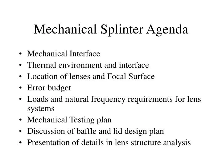
Mechanical Splinter Agenda. Mechanical Interface Thermal environment and interface Location of lenses and Focal Surface Error budget Loads and natural frequency requirements for lens systems Mechanical Testing plan Discussion of baffle and lid design plan

E N D
Mechanical Splinter Agenda • Mechanical Interface • Thermal environment and interface • Location of lenses and Focal Surface • Error budget • Loads and natural frequency requirements for lens systems • Mechanical Testing plan • Discussion of baffle and lid design plan • Presentation of details in lens structure analysis
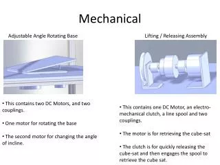
Mechanical Interface • Outer diameter of lens structure is 2600mm • Attach in 3 locations • Flexures should be radially compliant • Allow for movement in the direction of optical axis during integration (5mm sufficient?) • Discussion of possible designs of interface • FS interface discussion
Lens structure side view cross-section Outer ring Radial strut Inner ring
Thermal Interface • Schedule of thermal analysis • When front lens environment can be provided • When determine requirement for heaters on lens structure • Agreement on who provides what for thermal control • MSFC can provide heaters, sensors, cables, connections at mechanical interface • EUSO system to provide control, monitoring, switching, etc.
Lens system and FS locations • Lens 1 radius of curvature: 4717mm • 2nd surface of Lens 1 to aperture stop distance: 409.68mm • Aperture Internal Diameter: 2300mm • Aperture stop to 1st surface of lens 2: 1518 mm • Lens 2 Radius of curvature: -3496.5mm • 2nd surface of Lens 2 to FS distance: 1637.63mm • Based on spherical radius system with lens thickness arbitrarily chosen at 23mm. • Lens thickness will be updated to 15mm, which may slightly change optical component locations. • If aspherical design is chosen, these numbers will change significantly
Error Budget/Alignment • Discussion of sensitivity • Discussion of on-orbit focus potential Loads and Natural Frequency requirements • Plan of Alenia to perform analysis and provide loads and natural frequency
Baffle design plan • ISS to perform analysis by July • General discussion of sensitivity of design
OM Testing –Previous test plan Structural Environmental Test Modal Survey Static Load ?Acoustic? Clean OS Clean OS Clean OS Clean OS MSFC/4493 OS Short Form Optical Performance Test Effective Focal Length Lens/Petal Relative Alignment Check Wright Patterson MSFC/4619 Prototype, flight and spare OS Long Form Optical Performance Test Effective Focal Length (EFL) Entrance Pupil Diameter (EPD) Axial Color Field Curvature Transmission Relative Illumination Falloff Resolution Modulation Transfer Function Veiling Glare Lens/Petal Relative Alignment Check Flight and spare • Thermal Environmental Test • Thermal Vacuum • Thermal Cycling • Thermal Balance OS Short Form Optical Performance Test Effective Focal Length Lens/Petals Relative Alignment Check Test Location Key Testing will be conducted per written procedures by the US EUSO team with facility support as required.