Download
1 / 8
80 likes | 136 Views
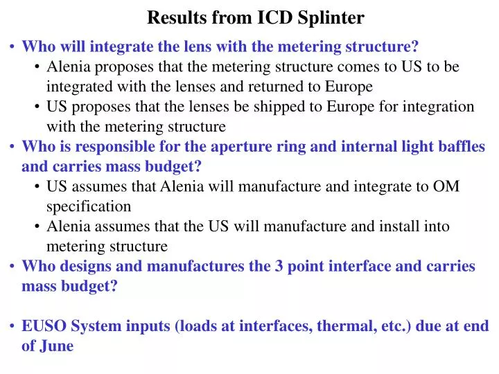
Who will integrate the lens with the metering structure? Alenia proposes that the metering structure comes to US to be integrated with the lenses and returned to Europe US proposes that the lenses be shipped to Europe for integration with the metering structure

E N D
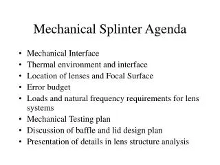
Who will integrate the lens with the metering structure? • Alenia proposes that the metering structure comes to US to be integrated with the lenses and returned to Europe • US proposes that the lenses be shipped to Europe for integration with the metering structure • Who is responsible for the aperture ring and internal light baffles and carries mass budget? • US assumes that Alenia will manufacture and integrate to OM specification • Alenia assumes that the US will manufacture and install into metering structure • Who designs and manufactures the 3 point interface and carries mass budget? • EUSO System inputs (loads at interfaces, thermal, etc.) due at end of June Results from ICD Splinter
CONTENT OF INTERFACE DEFINTION AND DESCRIPTION IRD 3.1 OM to EUSO Interface Characteristics and Functions · Need several schematic diagrams starting at a top level and working down to more detail showing where the lens fit in the structure and emphasizing the important interface (I/F) information. · Need a cross-section or exploded view of EUSO showing where the lenses are located. Show lens separation, distance to focal plane, and distance from entrance aperture. · Need a more detail diagram showing the attach points of the lenses to the EUSO structure. · Also need a figure showing the lens structure itself with attachment features. 3.2 Mechanical Requirements 3.2.1 Coordinate Systems · Coordinate system needs to be defined in a drawing. · Need top level drawings and working down to more detailed drawings showing where the lens fit in the structure and emphasizing the important interface (I/F) information. · Need a detail drawing showing the attach points of the lenses to the EUSO structure. · Need a detailed drawing showing the lens structure itself with attachment features. 3.2.2 Envelopes 3.2.2.1 Static · Need a detailed drawing defining each envelop (translation as well as tilt/tip) with tolerances for front and rear lenses.
CONTENT OF INTERFACE DEFINTION AND DESCRIPTION IRD 3.2.2.2 Dynamic · Need a detailed drawing defining the allowed motion (translation as well as tilt/tip) with tolerances of the static envelope during launch and ascent. 3.2.3 Mounting/Installation of Flight Hardware · Need detailed drawings for the mounting/installation of both lenses. · Provide a brief description of the installation process. Reference the installation procedures, which may be TBD at this time. 3.2.4 Ground Handling · Need figures showing the ground handling equipment as well as any test fixtures. · Need detailed drawings showing the attachment features of the equipment and fixtures to both lenses. 3.3 Structural Interface Requirements 3.3.1 Loads · Need analyses that provide the loads listed below at all the attach points of both lenses. 3.3.1.1 Acoustic 3.3.1.2 Transportation 3.3.1.3 Quasi-static/Vibration 3.3.1.4 Ground Handling 3.3.2 Structural Characteristics · Need requirement for the minimum frequency of fundamental vibration node.
CONTENT OF INTERFACE DEFINTION AND DESCRIPTION IRD 3.3.2.1 Material · Need any structural material requirements that define or prohibit material selection. 3.3.2.2 Stiffness · Need analysis to determine the minimum frequency of fundamental vibration node. 3.3.3.3 Electrical bonding/Grounding · Need requirements on electrical bonding/grounding. · Need detailed drawings showing electrical bonding/grounding. 3.3.3 Mass Properties · Need mass properties requirements allocations on weight/mass, cg plus tolerances, and moments of inertia plus tolerances. 3.3.3.1 Weight/Mass 3.3.3.2Center of Gravity 3.3.3.3 Moments of Inertia 3.4 Optical Performance Requirements · Need instrument requirements for performance parameters listed below. 3.4.1 Field of View 3.4.2 Throughput 3.4.3 Spot Size 3.4.4 Wavelength
CONTENT OF INTERFACE DEFINTION AND DESCRIPTION IRD 3.4.5 Chromatic Aberration 3.4.6 Baffle 3.4.7 Effective Focal Length 3.5 Environmental Interface Requirements · Need environmental requirements. 3.5.1 Thermal · Need thermal analyses defining thermal loads at conductive interfaces. 3.5.2 Contamination 3.5.3 Humidity 3.6 Operations Interface Requirements · Need to have requirements for operational GSE in addition to the afore mentioned ground handling GSE and test fixturing. 3.6.1 Ground Operations 3.6.1.1 Checkout 3.6.1.2 GSE
CONTENT OF INTERFACE DEFINTION AND DESCRIPTION IRD 3.7 Safety Interface Requirements · Need safety interface requirements for hazard analyses. 3.7.1 Design Safety 3.7.2 Flight Operations 3.7.3 Ground Operations 3.7.4 Range Safety 3.8 Reliability Interface Requirements · Need FMEA for Optical Module. 3.9 Maintainability Interface Requirements · Need requirements for engineering model, flight model and flight spare. 4.0 INTERFACE REQUIREMENTS VERIFICATION
PHASE A REQUIREMENTS Optics Module Mechanical Inputs (include tolerances) envelope of lens 1 mass property of lens 1 distance from lens 1 to aperture stop adjustment requirement for lens 1 diameter of entrance pupil diameter distance from aperture stop to lens 2 envelope of lens 2 mass property of lens 2 distance from lens 2 to focal surface adjustment requirement for lens 2 diameter of focal surface geometry of focal surface adjustment requirement for focal surface Optics Module Optical Inputs (include tolerances) Field of View Throughput Spot diameter Angular resolution Wavelength
PHASE A REQUIREMENTS External baffle (protect front lens from stay light, atomic oxygen and micrometeoroids) Internal baffle (scattered light) Outgassing/contamination requirements to protect optics Filter Subsystem Inputs (include tolerances) optical characteristics - transmission, red tail attachment mechanism dimensions of filter (bevels, thickness) EUSO System Inputs Loads at our interfaces Thermal environment Natural frequency Focal Surface Input dimensions of the MAPMT thermal environment (not needed at this time) loads at MAPAT/filter interface (not needed at this time) Joint OM and System Detail of interface (3-point, etc.) – US will provide first cut at this