Download
1 / 47
480 likes | 656 Views
Overview. v on Neumann Architecture Computer component Computer function Instruction set CPU Memory I/O. von Neumann architecture. All contemporary computer design are base on three key concepts : Data and instructions are stored in a single read-write memory.

E N D
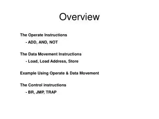
Overview • von Neumann Architecture • Computer component • Computer function • Instruction set • CPU • Memory • I/O
von Neumann architecture All contemporary computer design are base on three key concepts : • Data and instructions are stored in a single read-write memory. • The contents of this memory are addressable by location • Execution occurs in a sequential fashion from one instruction to the next
Computer Component • Arithmetic and Logical Unit (ALU) • Control Unit (CU) • Memory Unit • I/O devices • Central Processing Unit (CPU) • Storage devices • System bus
Computer Function • The basic function is program execution. • The Program to be executed consists of a set of instruction stored in memory. • The CPU does actual work by executing instructions specified in the program.
Instruction Sets • Instruction : An individual pattern which instructs the computer to do a task. • Consists of two part • OP-code • Operand or Address • Instruction set classifies CPU into model or family
Computer Component Central Processing Unit (CPU) • Processor • Where the data are manipulated by executing instruction • Two basic parts are • Control Unit (CU) • Arithmetic and Logical Unit (ALU)
Executing Instruction Instruction cycle • Fetch cycle : CPU read (fetches) instructions from memory one at a time. • Execution cycle : CPU executes each instruction
Instruction Cycle Start No Are the Instruction awaiting execution? Yes Fetch the next instruction Execute the instruction halt No Are there interrupts require services? Yes Transfer control to interrupt handling program
CPU Control Unit (CU) • Controls each part of components to perform instruction or program • procedure • load program into memory • fetch instruction one at a time • decode, create and send control signals
CPU Control Unit Components The CU has three components • Program Counter(PC): contains the address of the next instruction to be executed • Instruction Register (IR) : holds the actual instruction that is being executed • Instruction Decoder : determines the type of operation currently in the IR and sends control signal to implement that operation
Control Unit Function • Instruction sequencing : selects instruction from memory to executed • Instruction Interpretation : interprets and sends control signals to CPU through control lines
Instruction sequencing • PC = PC’ + K • PC : next instruction address • PC’: previous instruction address • k : instruction length 0 3 4 15 Op Code Address (a) Instruction Format 0001 = Load AC From Memory 0010 = Store AC To Memory 0101 = Add to AC from Memory (b) Partial List of Opcodes
300 301 302 PC AC IR 300 301 302 PC AC IR Example of program execution 3 0 0 3 0 0 1 9 4 0 1 9 4 0 0 0 0 3 5 9 4 1 5 9 4 1 1 9 4 0 1 9 4 0 2 9 4 1 2 9 4 1 CPU Registers . . . . . . . . . . . . 940 941 940 941 0 0 0 3 0 0 0 3 1 2 0 0 0 2 0 0 0 2 300 301 302 PC AC IR 300 301 302 1 9 4 0 PC AC IR 3 0 1 1 9 4 0 3 0 1 5 9 4 1 0 0 0 5 5 9 4 1 0 0 0 3 2 9 4 1 5 9 4 1 2 9 4 1 5 9 4 1 . . . . . . . . . . . . 316 + 216 = 516 940 941 940 941 0 0 0 3 0 0 0 3 3 4 0 0 0 2 0 0 0 2 300 301 302 300 301 302 PC AC IR PC AC IR 1 9 4 0 1 9 4 0 3 0 2 3 0 2 5 9 4 1 5 9 4 1 0 0 0 5 0 0 0 5 2 9 4 1 2 9 4 1 2 9 4 1 2 9 4 1 . . . . . . . . . . . . 940 941 940 941 0 0 0 3 0 0 0 3 5 6 0 0 0 2 0 0 0 5
Instruction Interpretation Control Unit Implementation Method • Hardwired Control Unit • Microprogram Control Unit C’’ in C” out C’ in C’ out ALU Input data Output data
CPU Arithmetic and Logical Unit (ALU) The ALU has two part • Functional unit : perform the operation (arithmetic operations and logical operations) • Register : hold operands, results, errors and status information
Arithmetic integer adder integer subtractor integer multiplier integer divider arithmetic shift unit incrementor & decrementor floating-point arithmetic unit Logical comparator logic shift unit NOT unit AND unit OR unit CPU Functional Unit
Arithmetic + add - subtract * multiply / divide ^ raise by a power Logical =, = equal, not equal >, > greater than, not greater than <, < less than, not less than >, > greater than or equal, not ... <, < less than or equal, not ... CPU Operation of functional unit
Left X Z := X op Y Z Result op Right Y E Error/Status ? Register Control signal Data CPU Diagram of functional unit Start/Stop signal from control unit Timing signal
CPU Register • high-speed memory location • contain data for functional unit • register size -> word size • 16-bit processor • 32-bit processor • 64-bit processor
Accumulator register : operand, result Index register : address Special-purpose register Overflow register Carry register Shift register Temporary register Stack register Floating-point register Status information register CPU Register Type • General purpose register
CPU Register & Memory • reference by name instead of unsigned binary address : A, R1 • higher speed than memory • use for specific job, not general job • use specific path for transfer data
Processor families • Intel : Pentium • AMD : K6, K7 • Cyrix : Cyrix • Motorola : 680X0
Computer Component Memory • Stores and retrieves (fetch) information • It is divided into cells, and data are accessed by means of the unique address of the cell. • 2n words of m-bit memory with addresses 0,1,2,…,2n-1
Access data in memory • Store นำข้อมูลเข้าไปบรรจุใน memory ณ ตำแหน่งที่ระบุ • Fetch ดึงข้อมูลจาก memory
Memory component • Memory Address Register(MAR): contains the address of the word we want to store or fetch • Memory Buffer Register (MBR) : contains the contents of the location we want to do with • Decoder : decodes address to be the location • Read/Write Control Lines : provides the signal to control the memory perform a fetch or store operation.
Memory component address 0000 0001 0002 0003 0004 … … … … … … 2n-1 Decoder MAR size Read control lines Write control lines MBR m-1 .. .. .. ... 2 1 0 Flow of information Control Signal Memory width
Read procedure • Stores address of data in MAR. • Sends read signal through read control line. • Decodes data in MAR to be the location in memory bank. • Reads data from that location and stores in MBR.
Write procedure • Stores address of data in MAR. • Stores data we want to write in MBR. • Sends write signal throgh write control line. • Decodes data in MAR to be the location in memory bank. • Writes data in MBR into that location.
Memory Hierarchy • Register • Caches : L1, L2, .. • Main Memory • Magnetic Disk • Magnetic Tape
Location CPU Internal External Capacity Word size Number of words Unit of Transfer Word Block Access Method Sequential Direct Random Associative Characteristics
Performance Access time Memory cycle time Transfer rate Physical type Semiconductor Magnetic surface Physical characteristics Volatile/Non-volatile Erasable/Non-erasable Characteristics (cont.)
RAM • Random Access Memory • EDO RAM (Extended Data-Out RAM) • DRAM (Dynamic RAM) • SRAM (Static RAM) • SDRAM (Synchronous DRAM) • DDR SDRAM (Double Data Rate SDRAM) • VRAM (Video RAM)
ROM • Read only memory : contain a permanent pattern of data for starting a computer to work • ROM Typed • PROM (Programmable ROM) • EPROM (Erasable ROM) • EEPROM (Electrical Erasable PROM)
Data in ROM • Important memory routines of system • Loader program • Compiler and interpreter • Important error-recovers procedures • some part of Operating System
Cache Memory • Disk cache • Memory cache • L1 cache : internal cache • L2 cache : external cache Word transfer Block transfer CPU Main Memory L2 Cache L1
Input/Output • I/O module • I/O function • I/O devices components • Data transfer Techniques
I/O Module • The entity with in a computer responsible for the control of one or more external devices and for the exchange of data between those devices and main memory and/or CPU register. • The major function for an I/O module • control and timing • CPU communication • Device communication • Data buffering • Error detection
I/O Function • The third key element of a computer is a set of I/O module. • Each module interface to the system bus or central switch and controls one or more peripheral devices. • I/O module contains logic for performing a communication function between the peripheral and the bus.
The Component of I/O devices • I/O Mechanism The mechanical, electrical that make up I/O devices • I/O Controller The component that manages the flow of information between the I/O device and the computer
Data Transfer Techniques • Programmed I/O • Interrupt Driven I/O • DMA I/O Controller
Programmed I/O • Data are exchanged between the CPU and the I/O module. • The CPU executes a program that gives it direct control of the I/O operation. • When the CPU issues to the I/O modules, it must wait until the I/O operation is complete. • If the CPU is faster than the I/O module, this is wasteful of CPU time.
Issue read command to I/O module CPU --> I/O Read statusof I/O module I/O --> CPU Not Ready Check status Error Condition Ready Read word fromI/O module I/O --> CPU Write word intomemory CPU --> Memory No Done? Programmed I/O Yes
Interrupt-Driven I/O • The CPU send START signal to I/O controller for start working. • After send signal, the CPU can continue their jobs • When I/O controller finish work, it send interrupt signal to the CPU • The CPU suspend their works and load data into memory
CPU --> I/O Issue read command to I/O module Do Something Else Read statusof I/O module Interrupt I/O --> CPU Check status Error Condition Ready Read word fromI/O module I/O --> CPU Write word intomemory CPU --> Memory No Done? Interrupt-Driven I/O Yes
DMA I/O Controller • Consist of 2 registers • DAR (DMA Address Register) : stores address of data in memory • WC (Word Count Register) : specifies data size to write in memory
DMA I/O Controller (cont.) • Store address of data in DAR • Store size of data in WC • Send START signal to I/O Controller • When finishing data transfer, it send interrupt signal to the CPU
CPU --> DMA Issue read block command to DMA module Do Something Else Read statusof DMA module Interrupt DMA --> CPU Direct Memory Access