Download

1 / 27
270 likes | 288 Views
EEG Biofeedback Final Report. Adrian Smith, gte198f Daniel Shinn, gte539f Ken Grove, gte262f ECE 4006 - Group N1 April 23, 2002. What is an EEG?. EEG stands for electroencephalogram EEG signals are created by measuring the difference in electrical currents across neuron membranes

E N D
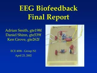
EEG BiofeedbackFinal Report Adrian Smith, gte198f Daniel Shinn, gte539f Ken Grove, gte262f ECE 4006 - Group N1 April 23, 2002
What is an EEG? • EEG stands for electroencephalogram • EEG signals are created by measuring the difference in electrical currents across neuron membranes • Electrodes attached to the body pick up these signals • There can be a only a few electrodes or many attached to the head
EEG signals • Many naturally occurring signals in the human body effect EEG signals • Frequency Analysis helps to separate the different signals
Types of EEG signals • EEG signals have been classified into 4 categories: • Delta 0.3 to 4 Hz • Dreamless sleep • Theta 4 to 8 Hz • Associated with thoughts which produce dreams • Alpha 8 to 13 Hz • Result of unfocused thoughts • Beta above 13 Hz • Result of interactions with environment
Electrode placement • Electrode placement can effect signals received
Related Research • Creating a Brain Computer Interface (BCI) has been a goal for researchers since computers were first introduced • BCI’s could help patients with motor disabilities use computers or mobility platforms • What is necessary: • Amplification • Filtering • Classification • Control
Related Research (cont.) • Large programs researching BCI’s: • Wadsworth Center in Albany • Graz University of Technology in Austria • Problems facing the programs: • Data transfer rate • Efficiency • Differences between test subjects • Learning curve for new users
Previous Semesters Work • Produced an amplifier that can output a strong enough signal to process with an Analog to Digital Converter • Created a baseline for our work with the amplifier and EEG signals
Our Focus • Purchase components needed to replicate the amplifier board • Assemble our amplifier board • Purchase and install an ADC board that can remain with the class for use in future semesters • Digitize the output signal • Interpret signals as commands for controlling a remote control vehicle • Output control commands to remote control vehicle
Amplifier Board • Built in previous semester • Based on Thomas Collura’s design, founder of Brainmaster • Two stage amplifier • 7805 voltage regulator power supply • Can use 9V battery or 6V-35V DC power supply
Stage 1 Gain of 50 Common Mode Rejection Ratio Provides noise reduction and signal centering Stage 2 Gain of 390 Capacitors stabilize power supply Amplifier Design
Resistors: (1) 10K 1/4W 5% (2) 1K 1/4W 5% (3) 130K 1/4W 5% (2) 200K 1/4W 5% (2) 10M 1/4W 5% (2) 200K 1/4W 5% (1) 51K 1/4W 5% Integrated Circuits: (3) OP-90 amplifiers (1) 620AN amplifier (1) LM7805C voltage regulator Capacitors: (1) 0.47uF 400V polypropylene (P474J) (3) 0.1uF 400V polypropylene (P104J) (2) 0.001uF 400V polypropylene (P103J) (1) 10uF 6.3VDC Tantalum Other: (1) Set of 3 conductor signal leads Amplifier Parts List
Analog-Digital Converter • Current board is a Keithley DAS-1701ST • Installed in borrowed computer • Must be moved but face PCI interface problem • Keithley KPCI-1307 card is the proposed solution
Keithley KPCI-1307 • 100k samples/sec • 16 single ended or 8 differential inputs • AutoZero capability filters out drift • 32 digital I/O • 3 clock/timer • drivers included • VHDL program or DriverLINX software options • Price : $680
VHDL Implementation • Download code to Flex10k20 chip on Altera board • Board receives signals from the KPCI-1307 and controls mechanical devices
DriverLINX Implementation • Create DLLs for data acquisition and signal routing • Interface can be programmed in • C • C++ • Visual Basic • Active X
Overview of Completed Objectives • EEG Amplifier • Order parts • Assembly • Testing • Data Acquisition Board • Order board • Installation of board • Installation of drivers and software
EEG Amplifier (Parts) • Resistors: (1) 10K 1/4W 5% (2) 1K 1/4W 5% (3) 130K 1/4W 5% (2) 200K 1/4W 5% (2) 10M 1/4W 5% (2) 200K 1/4W 5% (1) 51K 1/4W 5% • Capacitors: (1) 0.47uF polypropylene (P474J) [$1.62] (3) 0.1uF polypropylene (P104J) [$0.74] (2) 0.001uF polypropylene (P103J) [$0.45] (1) 10uF 6.3VDC Tantalum [$0.52] • Integrated Circuits: (3) OP-90 amplifiers [$2.35] (DIP package was not available when placing orders so SOIC package was substituted with the use of an 8-pin SOIC to DIP adapter. Price reflects cost of DIP package, as this should be ordered in future semesters.) (1) 620AN amplifier [$5.92] (1) LM7805C voltage regulator [$0.43] • Other: (1) Set of 3 conductor signal leads [$14.40] (3) Disposable electrodes for each testing session [$0.24] (1) Pre-holed circuit board [$8.49]
EEG Amp – Assembly and Testing Group N1’s Lab Rat EEG Amp Fully Assembled
Data Acquisition Board - Installation • KPCI-3107 • 16 analog single-ended or 8 analog differential. • 32 digital outputs • PCI interface • CAB-1284CC-2 • STP-36
KPCI-3107 (DriverLINX software) • Real-time data acquisition (with test panels) • Analog/Digital I/O programming • uses C++, VB, and Active X • Real-time Triggering via driver • allows user to specify trigger voltage and action to take after device is triggered.
Final Testing Waveforms AIO Test Panel with Sine Wave input to Channel A • The test panel allowed for verification that the acquisition board was functioning correctly • Eyebrow and eye blinks were recorded and graphed using the A/D board.
Board at End of Semester – A/D Board A/D board connected to Computer Amplifier connected to A/D board with electrodes
Ideas for Continuing the Project • Build a low-noise case for STP-36 break-out boards. • Calibrate gain for the EEG Amp input signal into an analog differential input channel. • Research and learn how to use programming knowledge into a DriverLINX program. • Program driver for KPCI-3107 board to output needed digital signal.