Download
1 / 14
140 likes | 144 Views
Explore various forms of requirements and how to organize them into a cohesive product design. Learn about input-process-output diagrams, functionalities, data, non-functionality, and more. Use case modeling is introduced as a transitional technique for requirements and product design specification.

E N D
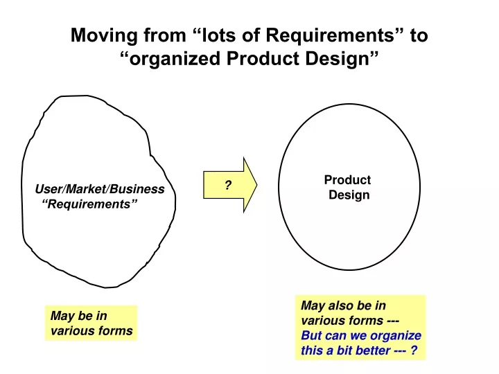
Moving from “lots of Requirements” to “organized Product Design” Product Design ? User/Market/Business “Requirements” May also be in various forms --- But can we organize this a bit better --- ? May be in various forms
One Way to “Transform” “transformed” form of Requirements One form of Requirements - Input-process-output (Activity Diagram, DataFlowDiagram & ERD & Use Case) - Business/Workflow - Functionalities - Add functionalities/interfaces (e.g. security check; portability) - Shorten functional algorithm (e.g. performance) - Data - Non-Functionality (constraints) • Screen Looks; Dialogue • sequence • - Database/File Design - U. I. • Pass Control and • Data exchange - System Interfaces
Where Do We Go with This? - Input-process-output (Activity Diagram, DataFlowDiagram & ERD & Use Case) process DB screens M-V-C - Add functionalities/interfaces (e.g. security check; portability) - Shorten functional algorithm (e.g. performance) . . . ? proc DB • Screen Looks; Dialogue • sequence • - Database/File Design U. I. P R O C proc Layered • Pass Control and • Data exchange How Do We “Decompose” & “Compose”
Top-Down / Hierarchical “Structural Breakdown” inputs outputs inputs outputs
Assembling Parts/ OO Approach Class A Class B Class C Class D
Let’s Look to Your Assignment for Clue“Model the Software to Describe Solar System” • Almost 90% (past classes) of the students provided: • Picture(s) of the solar system • A description of what this picture represents and how a user may interact with it to get more details: • A picture of the more “detail” of a specific planet • Any further interaction to get additional features • Modify the picture size of the planet • Rotate the planet • Get detail information about the planet Another word --- many of you described how “users” would a) evokethe solar system software and how “users” may b) interact with it Some used Activity Diagram to depict user “interactions” with the “Solar System” “pictures”and “sub-pictures” ----- the functionalitiesof the Solar System
A “Transitional Technique” for Requirementsor Product Design Specification - - > Use Case Modeling Use Case (a) Diagram Analyze & Organize the “function/features” Use Case(b) Description Requirements Document (pages of English Statements and Diagrams)
Scenario & Use Case in Use Case Modeling • Many of the “function and features” in the Requirements Document or Product Design may be viewed as “scenarios”: • Scenario: describes an set ofinteractionsbetween a “particular” individualand the system. (e.g. Joe moves the cursor to the start button and presses it; then the system displays the overall solar system panel within in .1 seconds ) • A Use Casegeneralizes the scenarios: describes the interactions (in general form) between an “actor” (abstract individual or another system or environment) and the system (e.g. A user presses the start button and the solar system software displays the overall solar system panel within .1 second ) Note: Many use “scenario’ and “use-case” interchangeably
(activity diagram) for Use Case Development Process Use Case Development Initial Req. Document: Docs Use Case Diagram & Description : Docs Initial Req. Document Study/rewrite scenarios Analyze the scenarios & pick the “actors” Rewrite the scenarios Into Use Cases Associate Actors to the Use Cases “Abstract” the Use Cases And Draw Use Case Diagram Use Case Diagram & Descriptions
Use Case Diagram • The diagram is made of the following: • Use cases (“functionality/feature” provided by the system) ---- in “bubble” diagram forms. • Actors (an external entity which interact with the use cases) ---- in a “stick figure” diagram forms • Association (relates the actors to the use case) ---- using lines • A frame (distinguishes the “system” and the external actors) ---- using a boundary line
UML: Use Case Diagram to represent Use Cases(this is a “static” model) High Level Steps (not necessarily always in sequence): • Analyze the scenarios • Decide on and create the system boundary • Identify the actor(s) • Convert the scenarios into abstract use cases • Describe the threads of activities that are necessary to support the actors’ needs; these threads of activities “expands” into more detailed use-case descriptions Solar System Display Static Solar System Extension pts : planets, sun <<include>> users rotate picture <<extends>> <<include>> Display Individual item details System startup/ shutdown In reality, we iterate over these steps! system admin & support
Reviewing the Use Case Diagram • Use Case Diagram should be “reviewed” for: • Allmajor functionalities and features to be provided by the product is included (completeness) • Check against the requirements list for completeness in coverage • Make sure that there is no duplication nor inconsistency within and among the use cases. • Make sure that all actors(completeness) are included.
UML: Use Case Descriptions(this provides a bit more“dynamic” model) • A Use Case Description is a specification of the interaction between the actor(s) and the use case in system(product): • Specifies the actions by the actor • Specifies the system responses to the actions • There is no one standard notation for Use Case Descriptions • You can include any of the “forms” or pictures • but preferred one is “text”
A Sample Use Case DescriptionTemplate See example –page 170 of your text • Use Case Name or/number: (for identification purpose) • Actors: agents participating in the use case • Stakeholders & needs: identify those who have the needs for this use case (e.g. sources of this requirements) • Pre-Conditions: conditions that must be true prior to the activity or operation • Post-Conditions: conditions that must be true when the operation or activity completes • Trigger: an event that causes the use case to begin • Basic Flow: A description of the flow of interaction between the actor(s) and the product use case • Extensions : description of alternative flow of interaction from the normal flow, such as an error processing flow. Meat Of Descrip. Note: We may include diagrams (such as the activity diagram or the pictorial representation of the UI screens) in the Use Case Description.

![[Product name]](https://cdn1.slideserve.com/1898631/product-name-dt.jpg)