Download
1 / 36
450 likes | 1.28k Views
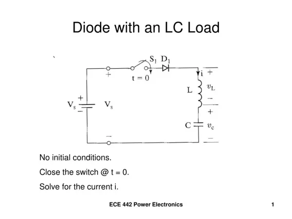
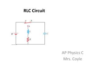
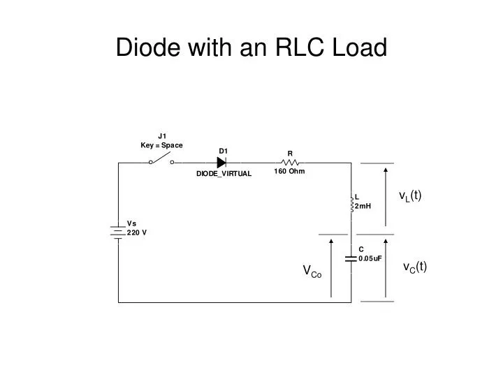
Diode with an RLC Load. v L (t). v C (t). V Co. Close the switch at t = 0. V Co. KVL around the loop. Characteristic Equation. 3 Cases. Case 1 = ω 0 “critically damped” s 1 = s 2 = - roots are equal i(t) = (A 1 + A 2 t)e s1t. 3 Cases (continued). Case 2

E N D
Diode with an RLC Load vL(t) vC(t) VCo
3 Cases • Case 1 • = ω0 “critically damped” • s1 = s2 = - • roots are equal • i(t) = (A1 + A2t)es1t
3 Cases (continued) • Case 2 • > ω0 “overdamped” • roots are real and distinct • i(t) = A1es2t + A2es2t
3 Cases (continued) • Case 3 • < ω0 “underdamped” • s1,2 = - +/- jωr • ωr = the “ringing” frequency, or the damped resonant frequency • ωr = √ωo2 – α2 • i(t) = e-t(A1cosωrt + A2sinωrt) • exponentially damped sinusoid
Determine the conduction time of the diode • The conduction time will occur when the current goes through zero.
Freewheeling Diodes Freewheeling Diode
Freewheeling Diodes • D2 is reverse biased when the switch is closed • When the switch opens, current in the inductor continues. D2 becomes forward biased, “discharging” the inductor.
Analyzing the circuit • Consider 2 “Modes” of operation. • Mode 1 is when the switch is closed. • Mode 2 is when the switch is opened.
Circuit in Mode 1 i1(t)
Circuit in Mode 2 I1 i2
Recovery of Trapped EnergyReturn Stored Energy to the Source
Add a second winding and a diode “Feedback” winding The inductor and feedback winding look like a transformer
Equivalent Circuit Lm = Magnetizing Inductance v2/v1 = N2/N1 = i1/i2
Operational Mode 1Switch closed @ t = 0 Diode D1 is reverse biased, ai2 = 0
Vs = vD/a – Vs/a vD = Vs(1+a) = reverse diode voltage primary current i1 = is Vs = Lm(di1/dt) i1(t) = (Vs/Lm)t for 0<=t<=t1
Operational Mode 2Begins @ t = t1 when switch is opened i1(t = t1) = (Vs/Lm)t1 = initial current I0 Lm(di1/dt) + Vs/a = 0 i1(t) = -(Vs/aLm)t + I0 for 0 <= t <= t2
Find the conduction time t2 Solve -(Vs/aLm)t2 + I0 = 0 yields t2 = (aLmI0)/Vs I0 = (Vst1)/Lm t1 = (LmI0)Vs t2 = at1
Example 2.8 • Lm = 250μH N1 = 10 N2 = 100 VS= 220V • There is no initial current. • Switch is closed for a time t1 = 50μs, then opened. • Leakage inductances and resistances of the transformer = 0.
Determine the reverse voltage of D1 • The turns ratio is a = N2/N1 = 100/10 = 10 • vD = VS(1+a) = (220V)(1+10) = 2420 Volts
Calculate the peak value of the primary and secondary currents • From above, I0 = (Vs/Lm)t1 • I0 = (220V/250μH)(50μs) = 44 Amperes • I’0 =I0/a = 44A/10 = 4.4 Amperes
Determine the conduction time of the diode • t2 = (aLmI0)/Vs • t2 = (10)(250μH)(44A)/220V • t2 = 500μs • or, t2 = at1 • t2 = (10)(50μs) • t2 = 500μs
Determine the energy supplied by the Source W = (1/2)((220V)2/(250μH))(50μs)2 W = 0.242J = 242mJ W = 0.5LmI02 = (0.5)(250x10-6)(44A)2 W = 0.242J = 242mJ