Download

1 / 53
530 likes | 623 Views
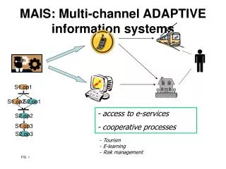
Development of Rigorous Adaptive Information Systems. Dr. Nasreddine Aoumeur FIN, ITI, DB group aoumeur@iti.cs.uni-magdeburg.de Course Site: wwwiti.cs.uni-magdeburg.de/~aoumeur wwwiti.cs.uni-magdeburg.de/iti_db/lehre/oois/inde. Information Systems: Working definition.

E N D
Development of Rigorous Adaptive Information Systems Dr. Nasreddine Aoumeur FIN, ITI, DB group aoumeur@iti.cs.uni-magdeburg.de Course Site: wwwiti.cs.uni-magdeburg.de/~aoumeur wwwiti.cs.uni-magdeburg.de/iti_db/lehre/oois/inde ... Information Systems
Information Systems: Working definition • reactive systems (i.e. in continuous interaction with their environment), with • large amount of immutable and non-immutabledata(i.e. fixed and changing) and, with • processes and activities for exhibiting behaviors on these (state-less and –full) data. ... Information Systems
Conceptual Modelling of IS in general Structural aspects State-less and -ful DATA E /R or Object paradigm Behavioural aspects Processes and Rules Petri Nets ... Information Systems
Conceptual Modelling of IS in UML • State-less and stateful DATA • - Use Cases • - Class Diagrams • - Object Diagrams • Object Constraint Language Structural aspects Forall C in …. • Processesand Rules • - Sequence Diagrams • - Collaboration Diagrams • - State Diagrams • Activity Diagrams • Component / deployment diagrams (implementation) Behavioural aspects ... Information Systems
Airport Flight Passenger Conceptual Modelling of IS in UML View-oriented system modelling Information system partial views Use caseArrival Includes Landing Description The plane is landing. Then the passengers deplane and the luggage is unloaded. If the passenger has luggage then the passenger claims its luggage. . . . . UML diagrams ... Information Systems
The origins of UML UML : Overview and History UML resulted from the merging of three very popular OOD methods - ---The three-Amigos Jacobson’s Use-Case approach This focused on the external actors interacting with the system and their functional requirements.. A CASE tool called Objectory is available. Booch’s OOD Booch’s method developed originally in 1991 based on OO Diagrams rather complex and CASE tool support essential. The emphasis here was on design and implementation. Rumbaugh’s OMT Object modeling technique supported by OMTool. Very Straightforward approach with an excellent text book. Widely adopted in academia and industry alike. Focus very much on analysis rather than design and implementation. ... Information Systems
UML : Overview and History . . . What is UML • A Conceptual Modeling • Used to describe asimplified (abstract) view of reality • in order tofacilitate thedesign and then the implementation ofobject-oriented software systems • Conceptual Language • UML is primarilya graphical languagethat follows a precise syntax. • A UNIFIED • As By the start of the 90’s there was a flood of modeling languages, each with itsown strengths and weaknesses. ... Information Systems
UML : Overview and History . . When is UML • In 1994 the UML effort officially began as a collaborative effort between Booch and Rumbaugh. Jacobson was soon after included in the effort. • The goal of UML: • A comprehensive modeling language (all things to all people) that • Promotion of the communication between all members of the development effort. • Version : UML 1.0 …. UML 2.0 (2003) ... Information Systems
UML : Overview and History . . What is UML • UML is a language • Conforms tospecific rules. • Allows the creation of (structural, behavioural, and functional)various models. • Does not tell which models need to be created. • UML is a languagefor visualizing • UML is agraphical language. • Pictures facilitate communication (a picture is worth a thousand words) • UML is a language forconstructing and understanding • UML supports both forward and reverse engineering. • UML is a language forsupporting analysis, specification and design • UML is intended primarily forsoftware-intensive information systems ... Information Systems
UML : Overview and History . . What is UML • Diagrams: • Structural aspects : • Class and object diagrams • Component and deployment (implementation) • OCL (object constraints language)for invariants, pre- and post-conditions. • Behavioural aspects : • Use cases, • Statechart, • Activity diagrams • Sequence diagrams • A set of standardised diagramatic notations for representing different aspects of a (information) system. Containing static structural views, dynamic behavioural views and functional views ... Information Systems
The Unified Modelling Language UML : Overview and History . . UML is NOT • A design method or process, neither is it a methodology. • There is no provision for project management • specification of deliverables or life cycle or provision • for estimation • Users, developers can uses • - Whatever process and life cycle – RAD they want • - Focus on Prototyping / incremental development • - Focus on waterfall or spiral - they wished and • - Provide their own project management and QA • framework. ... Information Systems
UML : Overview and History . . Inside UML • Static, structure diagrams • Class and instance diagrams • These depict the components (classes or instances) within the • system, • Their attributes and methods and their relationships with • each other • The class diagram in particular is the most important single • diagram in the design • Plus OCL constraints on invariants pre- and post-conditions • on methods • Component and subsystem diagrams (implementation) • - How classes are grouped to form large assemblies - • reusable components, sub-systems or packages of classes. • Deployment diagrams (implementation) • - How the software components are deployed across a set • of hardware components. ... Information Systems
UML : Overview and History . . Inside UML • Interaction diagrams • Use-case diagrams • - Show the interface between the system and the outside world • - Identify the actors in the system and their required • functionality. • Sequence diagrams • - Capture the functionality of the system suing the messages • passing between objects. • - Each sequence diagram shows the implementation of one • scenario • Collaboration diagrams • - Based on the instance diagram, it shows how specific • scenarios are implemented by message sequence. • - Similar to sequence diagrams but with more detail ... Information Systems
UML : Overview and History . . Inside UML • Dynamic behaviour of the system • Activity diagrams • - Similar to Petri-nets, • - Provide a view of the way objects interact and changes • their states in consequence • - The emphasis here is on system functionality as • perceived by users • Statecharts • - Harel Statecharts are developed from finite state • notation • - Illustrate the dynamic behaviour of objects. i.e. the way • in which an object evolves through time • - in response to external events. ... Information Systems
UML : Overview and History . . UML for IS • Most diagram types are involved, but principally at the conceptual level : • Conceive a use-case diagram • - identify actors • - identify major functional requirements • Conceive an initial Class diagram • - discover principle classes • - represent important relationships • Event sequence diagrams • - Examine possible object interactions • - Determine class protocols • At Implementation model different refinements are to undertake • - combining or splitting classes, - adding or removing • relationships, -defining the implementation of • relationships, - introducing generalisations, interfaces • - Introduce Component, sub-system and deployment models. ... Information Systems
UML : Use Cases Overview and illustrations A use case ... • Specifies what systemwill be used for, before the defining what system is supposed to do • Describe functionality ofa systemyielding observable results • Details scenarios that describe the interaction/dialog between users of the system and the system itself. Identify who (or what) interacts with the system • Does not indicate how the specified behavior is implemented, only what the abstract behavior is. • Performs a service for someusersof the system. • A user of the system is known as anactor. • An actorcan be a person or another system. • During the conceptual phase • Facilitates communication between the usersand developers of the system. • Facilitates the goal-based understanding of the system ... Information Systems
UML : Use Cases Basic artifacts Actor Relationship UseCaseName An Actor is consistent set of roles that user plays when interacting with the system (e.g. a user or outsider of the system that interacts with the system) A Use Cases a sequence of actions performed by a system that yields a valuable result for a particular actor A link between the actors and the functions (use-cases). Different relationships are possible. ... Information Systems
UML : Use Cases basic artifacts System Systemdefines the boundary between the system and the actors interacting with the system and other systems ... Information Systems
UML : Use Cases---Modelling guidelines • Model with use cases essencial parts of system functionality • Model only those actors who involved in Use Cases • Factor out common functionality using inheritance relationship <<include>>,<<extend>> stereotypes • Describe only those events which are visible for the actor • Eachuse caseshould describes a significant piece of system usage understandable by domain experts • Use nouns and verbs accurately to help deriving objects and messages for interaction diagrams afterwards ... Information Systems
UML : Use Cases basic artifacts Specifies the participation of an actor in a Use Case Actor Association Use Case A taxonomic relationship between a less and a more general Use Case Generalization ... Information Systems
UML : Use Cases basic artifacts Specifies how the behaviour of the extension use cases e can be inserted into the behaviour of the base use case b <<extend>> e b Extend a relationship Specifies how the behaviour of the included p contributes to the behaviour of the base use case b <<include>> b p specialize a relationship ... Information Systems
UML : Use Cases actors illustrations Louis acts as a student Enroll for a course Student Prepare for examination Deposit funds Elen acts as a student ... Information Systems
UML : Use Cases actors illustrations Louis acts as a student Enroll for a Course Student Prepare for Examination Louis acts as a customer customer Deposit funds ... Information Systems
UML : Modeling scenarios with Use Cases Ask the following questions: • What are the primary tasks that the system is supposed to perform? • What data will the actor manipulate (add, store, change or remove) in the system? • Which external changes does the system need to know about? • Which changes or events will the actor of the system need to be informed about? ... Information Systems
UML : Modeling scenarios with Use Cases To model the requirements of a system … • Identify all actors(users of the system). • Identify the needs, from the system, of each individual actor. • Make each need a use case. • Identify redundant behavior within your set of use cases, and factor it into common base-class use cases ( generalization ) . • Do the same for actors. • Show the relationships between actors and use cases. ... Information Systems
UML : Use Cases concepts Use case diagrams … • Show a set ofactors, use cases, and their relationships. • Facilitate communication between non-technical customers and developersdue to their simplistic nature. • Show the functionality of the system from the prospective of each user of the system. • Model thecontextof the system. • Model therequirementsof the system. ... Information Systems
UML : Use Cases --- AIRPORT illustration • Use caseArrival • Includes Landing • Actors plane,passenger • Preconditions non • Description The plane is landing. Then the passengers deplane and the luggage is unloaded. If the passenger has luggage then the passenger claims its luggage. ... Information Systems
Airport Passenger Plane UML : Use Cases --- AIRPORT illustration use case <<include>> use case TakingOff Departure actor actor <<include>> Arrival Landing Flight ... Information Systems
UML : Use Cases --- ATM use illustration Automated Teller Machine (ATM) Withdraw Cash Transfer Funds Bank Consortium Customer Deposit Maintain ATM MaintenanceCrew ... Information Systems
browser manager Staff borrower student borrower Counter staff Return late book UML : Use Cases --- Library illustration Use-case for library system Check member status <<uses>> Borrow book Register member <<uses>> Reserve book Usage report Return book Update catalogue Browse catalogue <<extends>> ... Information Systems
UML : Class Diagrams Overview • Class diagramsare the most commonly used diagrams in UML • Class diagramsare forvisualizing, specifying and documenting the system from astatic perspective • Class diagrams indicate which classes know about other classes and, if they do, • what type of relationship exists ... Information Systems
UML : Class Diagrams Overview • Class diagrams will have different levels of detail (abstraction) depending on where we are in the software development process • Class diagrams commonly contain classes, interfaces, collaborations and associations • Class diagramshelp in showing the functional requirements of the system - the services the system should provide to its end users ... Information Systems
UML : Class Diagrams concepts Compacted ... Information Systems
UML: Class Diagrams---Modelling Guidelines • To model a collaboration (a group of classes working toward a common purpose) … • Use scenarios to see which classes are actually involved in carrying out a particular operation. • Scenarios will also aide in establishing relationships between classes. • Fill in the ‘responsibilities’ section of each class icon. • The responsibilities of each class will eventually evolve into actual attributes and behaviors. • A complex system typically requires multiple class diagrams. • Each diagram is devoted to a particular functionality of the system. ... Information Systems
UML: Class Diagrams---Modelling Guidelines • Multiple class diagrams are required to model large systems. • Each individual class diagram … • Shows a single aspect of the system. • Contains only elements that are essential to understanding that aspect. • Provide details consistent with its level of abstraction. • Uses meaningful class and member names • Pointersto other classes are modeled asassociations ... Information Systems
UML: Class Diagrams---Modelling Guidelines • A well-defined class is: • loosely coupled (few entry points) and • highly cohesive (all members toward one functionality) • Ask yourself “Am I trying to show whatthe class does or how it does it”. • That will tell you at what level of abstraction to model the class. • In the requirements and specification phase you are interested in “what”. • In the design phase you are interested in “how”. • Don’t hesitate to attach notes to the class icons • if further clarification is necessary. ... Information Systems
UML : Class Diagrams---Illustration ... Information Systems
UML : Class Diagrams---Association types The UML recognizes four principle relationships between classes as follows :- Simple association - usually annotated and interpreted left to right/top to bottom. use small arrows to indicate. Aggregation - ‘a part of’ relationship Composition - a stronger - permanent ownership form of aggregation. Generalisation/specialisation – ‘is a’ or ‘is like as’ relationship. course is enrolled on student * race car 4 wheel car car vehicle ... Information Systems
worker * employee 0,1 boss works for <<interface>> Controls maths Flight model controls simulator type collection <<bind>> book Book list UML : Class Diagrams---Association types Other forms of notation frequently used are :- Role names on associations Interface inheritance (implements) Uses relationship: Generic instantiation : ... Information Systems
Book author title Book author title lend return reserve UML: Class Diagrams--Attributes / Methods • During the conceptual modelling phase: • the conceptual class diagram model is developed • through the following stages :- • Simple class names with relationships • Introduction of class attributes • Introduction of methods • During design the design phase, • attribute and method detail will • be extended to include visibility indication, • (2) data types, parameter and parameter types • and return types from methods. Book ... Information Systems
UML: Class Diagrams—Visibility and Scope • Visibility • Class members (attributes and behaviors) may be specified as public (+), private (-) , or protected (#). • Restricting visibility is the same as restricting accessibility. • limiting the number of entry points into an object. • Scope • Individual member data (attributes) may have eitherclassscope orinstancescope. • Class scope - A single copy of an attribute is shared by all instances of a class (underline the attribute) • productCount : int • In C++ : static int productCount • Instance scope - Each instance of a class would have its own copy of the attribute. • All attributes have instance scope by default ... Information Systems
UML: Class Diagrams—Visibility and Scope ... Information Systems
UML: Class Diagrams — Abstract / Polymorphism • Abstract • A abstract classcannot have any direct instances. • Not all OO programming languages directly support abstract classes. • An abstract class is thought to be so general as to be useless by itself. • Abstract classes only occur in the context of an inheritance hierarchy. • In UML you specify that a class is abstract by writing its name in italics. ... Information Systems
UML: Class Diagrams — Abstract / Polymorphism • Polymorphism • Polymorphic behavior exists in the context of inheritance. • Polymorphism applies to behavior (member functions) only. • Polymorphism is synonymous with dynamic binding. • In UML a behavior name in italics is used to indicate polymorphism. ... Information Systems
UML: Class Diagrams —Abstract / Polymorphism ... Information Systems
UML: Class Diagrams-More Concepts-Multiplicity • Multiplicity • Class multiplicity • In UML it can be indicated by placing a number in the upper right corner of the class icon. • Most commonly expressed in the context of associations between classes. • Attribute multiplicity • In UML it is indicated as an expression appearing in square brackets just after the attribute name. ... Information Systems
UML: Class Diagrams --More Concepts-Attributes • Attributes • May be expressed using various levels of detail. • The syntax for an attribute is • [visibility] name [multiplicity] [: type] [ = initialValue ] [{propertyTag}] • There are three predefined property tags • changeable - the attribute may be read and modified (default) • addOnly - when multiplicity > 1, additional objects may be added but not removed • frozen - read only (constant value) • The only feature of an attribute that is required in a class icon is its name. ... Information Systems
UML: Class Diagrams-More Concepts-Operations • Operations (behaviors) • May be expressed using various levels of detail. • The syntax for an operation is • [visibility] name [(parameterList)] [: returnType] [{propertyTag}] • Predefined propertyTags are ... • isQuery - cannot change the state of the object. • Sequential - only one thread of control in the object at a time. • Guarded - pretty much the same as sequential • concurrent - multiple threadsof control may be in the object simultaneously. • Each parameter has the syntax: • [direction] name : type [= defaultValue] • Directions may be in, out, or inout. • The only feature of an operation that is required in a class icon is its name. ... Information Systems
UML: Class Diagrams —More Concepts-Template • Templates are ... • A parameterized element, intended to facilitate software reusability. • Used to automate the creation of class definitions. • Essentially a class definition with the data types of certain attributes yet to be defined. • Most commonly used to create container classes. • Represented in UML as a dashed box in the upper right-hand corner of the class icon, which lists the template parameters. ... Information Systems
UML: Class Diagrams —More Concepts-Template ... Information Systems