Download
1 / 15
150 likes | 241 Views
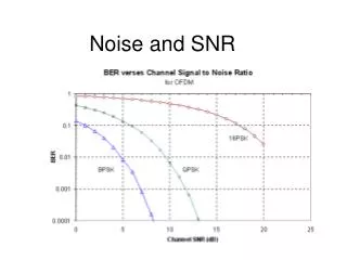
Charts for TPF-C workshop SNR for Nulling Coronagraph and Post Coron WFS. M. Shao 9/28/06. Depth of Dark Hole vs Starlight Suppression. 10 7. 10 -10 scattered light level @ 3~4 l /D implies ~ 10 -7 suppression of starlight. Star image without a coronagraph. Top level error budget

E N D
Charts for TPF-C workshop SNR for Nulling Coronagraphand Post Coron WFS M. Shao 9/28/06
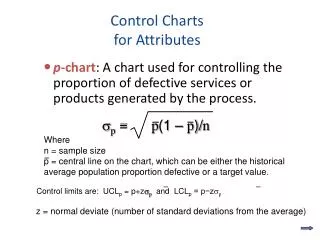
Depth of Dark Hole vs Starlight Suppression 107 • 10-10 scattered light level @ 3~4 l/D implies ~10-7 suppression of starlight Star image without a coronagraph Top level error budget OPD leak 4e-8 Amp leak 3e-8 Pol&color 3e-8 Total 1e-7 Blue means per sub aperture control 2/3 of residual starlight is random, spread over 1000 airy spots Star image suppressed by 107
Wavefront Sensing Principles • 1) need to sense the wavefront “AFTER” the coronagraph. This reduces the accuracy needed from the wavefront sensor. If the E field after the coronagraph is measured to 10%, the next iteration of the WFS servo can improve the null by 100:1. • Low accuracy in a post coronagraph WFS means more iterations to converge (from1e-3), but doesn’t affect convergence. • Low accuracy in a pre-coronagraph WFS means you never get to 1e-7 (1e-10/airy spot) • Inside an optical fiber there are only 2 quantities • Amplitude • Phase • In 2 polarizations, over ~20% bandpass
Nuller Architecture for Planet Imaging Science Camera Fiber Array Telescope Pupil Nuller #2 Dark output Spectrometer Calibration Wavefront Sensor Nuller #1 Bright output
Simplified Nuller/WFS • Nulling interferometer has bright and dark output • Dark output (star suppressed) goes through a fiber array. • DM in 1 arm of nulling interferometer • DM at a pupil • Pupil relayed to fiber/lenslet array (input) • Output of fiber array (new pupil) relayed to WFS CCD • Wavefront sensing (amp and phase) sensed at pupil, corrected at pupil. • We had looked at 3 other options Nulling Coronagraph DM (segmented) Beamsplitter Phase - Shifting Mirror Beamsplitter C C D Sampling Beamsplitter Beamsplitter S c i e n c e C a m Spatial filter e r a Fiber/lenslet array S c i e A n r r c a e y
Measuring Amp, Phase • Look at just the nuller first Science camera At image plane DM shutters Dither mirror WFS camera at Pupil plane For now 1 pixel/fiber
Measuring Amp, Phase • Look at just the nuller first Science camera At image plane DM shutters Dither mirror WFS camera at Pupil plane For now 1 pixel/fiber
Measuring Amp, Phase • Look at just the nuller first Science camera At image plane DM shutters Dither mirror Intensity mismatch leakage (DI)2/8 < 3x10⁻⁸ DI < 4.9x10-4 => N ~4.2x10⁶ photons for each of 1000 fibers WFS camera at Pupil plane For now 1 pixel/fiber
Measuring Amp, Phase • Look at just the nuller first Science camera At image plane DM shutters Dither mirror WFS camera at Pupil plane For now 1 pixel/fiber For l=550nm Leak = (Df)2/4 < 4e-8 Df < 4x10⁻⁴ radians ~ 35 pm
OPD Dither 3 points • In this example, dither is +/- 1nm. The null is 0.1 nm off. • B is at 3.3x10⁻⁷ (10x too large) • Offset ~(A-C)*0.1nm/(P*1.3x10-5) • P is flux at peak • Systematic errors • Dither stroke error becomes a gain error. 1.1nm stroke would make a 0.1nm error signal => 0.11nm • Photon noise • sx = (sqrt(A+C)/P)*(0.1nm/1.3e-5) • Total # ‘detected’ photons = 4x106 => sx = 31pm C A B 5 mag star => 20% bw@550nm => 2.9x10⁹ phot/sec into 8*3.5m telescope Need total of 8x10⁹ photons to sense amp, phi If QE, coatings are all 100%, need 3 sec. In practice 6~10sec?
Deep W.L. Null 1.5x10⁻⁹/airy spot • Max light into single mode fiber ~10nm (650nm 20%bw) • Light attenuated (~3000x) to 3 picowatts for deep w.l. null experiment. • Control update could be as high as a few hz. • Average null over 60 sec ~1.5x10⁻⁹/airy spot 3 picowatts thermal whitelight bulb -> fiber atten by ~3000x Dark count ~78 p/s Deep WL null
Bright Ref Beam Science Camera Fiber Array Telescope Pupil Nuller #2 Dark output Spectrometer Calibration Wavefront Sensor Nuller #1 Bright output • Combine in pupil • detect in pupil • Detect in image • Combine ref (pupil) with image (~Giv’on) • Combine ref (image) with pupil 4 ways of using a bright ref beam. Purpose (advantages) and requirements on the ref beam
Why Pupil / Pupil WFS? • Combine in pupil • detect in pupil • Detect in image • Combine ref (pupil) with image (~Giv’on) • Combine ref (image) with pupil Speckle smearing with l. Very high dynamic range detector needed. Complex processing to go from image to pupil DM actuation, with unknown noise prop. Pupil plane interferometry Pupil detection Ref image with speck pupil. Very high dynamic range detector needed. Combine flat wavefront with converging wavefront.. Ref pupil with speckle image Combine flat wavefront with converging wavefront. (limited bandwidth) Speckle smearing with l.
Bright Reference, Heterodyne Gain • A post coronagraph WFS is looking at the residual starlight after almost all the starlight has been removed. At this point other noise sources will dominate over photon noise. • Residual starlight 1e-7 (of the star) (from which the servo error signal is derived)(but in 1 out of 1000 fibers) • Local and Exo-zodi (into A*W ~ l2) Because the fiber is single mode, the local/exo-zodi per fiber is = image plane in 1 airy spot • Airy spot gets 1.222 more background • CCD read noise • CCD dark current • If a bright ref beam is interfered with a faint signal the Visibility is • Vis=2*sqrt(A*B)/(A+B) • If A =106 B= 1, the fringe signal is 2000. • Because the fringe singal has grown, it now dwarfs the noise from the CCD and zodi. • The fringe Vis of the Bright ref + faint residual starlight is used in place of the intensity of the faint residual starlight.
Background Noise • Residual starlight 10-10 of 5mag star 30 mag/airy spot • Local zodi @ 45deg 1.4* 22 mag/sqas • Exozodi (of a solar system clone) @ 45deg 2.8*22mag/sqas • Airy spot (50% lyot aperture) 1.22*l/5.3m • 4.2*Zodi ~ 27.6 mag/airy spot ~ 10x brighter than residual starlight • The bright reference is only used to improve SNR, the phase of the ref wavefront does not bias the result. • There is no need for a high quality 0.001l, ref wavefront.