Download
1 / 42
420 likes | 441 Views
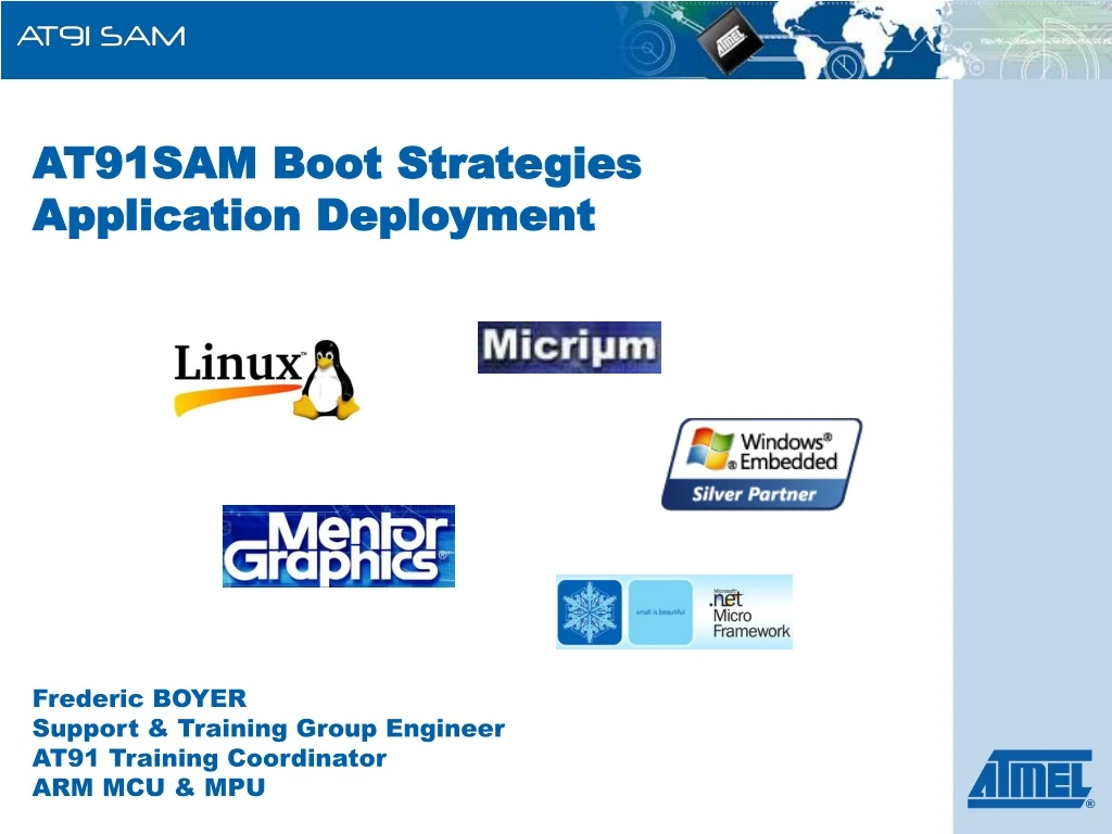
AT91SAM Boot Strategies Application Deployment. Frederic BOYER Support & Training Group Engineer AT91 Training Coordinator ARM MCU & MPU. Outline. Introduction Boot Solutions Application Deployment NVM Programming Solutions. 1. Introduction. 1. Introduction. NAND vs. NOR Flash.

E N D
AT91SAM Boot StrategiesApplication Deployment Frederic BOYERSupport & Training Group EngineerAT91 Training CoordinatorARM MCU & MPU
Outline • Introduction • Boot Solutions • Application Deployment • NVM Programming Solutions
1. Introduction NAND vs. NOR Flash Advantage of NAND High Speed Program/Erase Low Cost-per-bit High Capacity Advantage of NOR High Speed Random Access Byte Programming Code execution Disadvantage of NOR Slow Program Speed Slow Erase Speed Disadvantage of NAND Slow Random Access Time Difficulty of Byte Programming Applications Suitable for Code Memory eXecute In Place (XIP) Applications Suitable for Data Memory Program/Data Mass Storage
1. Introduction NOR vs. NAND Boot Considerations • NOR Flash • Used as an eXecute In Place (XIP) memory: no need to copy the program into RAM • Used to replace ROM • NAND Flash • Programs stored cannot be executed directly • Code Shadowing must be performed: memory contents must be first copied into memory-mapped RAM and executed there • Used to replace Hard Disk Drive
1. Introduction AT91SAM Boot Strategies Introduction • To ensure maximum boot possibilities, memory layout can be changed with different parameters. • On our AT91SAM, either GPNVM bit or BMS pin is responsible for the boot memory selection: • GPNVM bit for embedded flash µC: SAM7, SAM9XE. • BMS pin for the others: SAM926x, SAM9G20, SAM9R(L)… GPNVM bit (EmbeddedFlash based µC) BMS pin (Flashless µC) OR Power Up Boot Memory Selection
1. Introduction AT91SAM Boot Strategies Introduction (cont.) • Regarding GPNVM bit or BMS pin state, the µC will either: • Boot from ROM • Or Boot from the XIP memory (internal or external Flash) Boot Memory Selection Boot From ROM Boot From (Int. or Ext.) Flash OR
GPNVM bit = 1 1. Introduction Boot Memory Selection for Flash based µC(SAM7 and SAM9XE) • GPNVM bit is sampled when VDDCORE is powered. • GPNVM can be: • Set thanks to the EFC Controller • Cleared thanks to the EFC Controller or by asserting the ERASE pin. Power Up No Yes Boot From ROM Boot From Embedded Flash
BMS pin = 1 1. Introduction Boot Memory Selection for Flashless µC(SAM926x, SAM9R(L), SAM9G20) • BMS pin is sampled when VDDCORE is powered. Power Up Yes No Boot From ROM Boot From External 16-bit Flash
2. Boot Solutions Booting From an eXecute In Place Memory • XIP Memories used for booting purpose are: • Embedded Flash (SAM7, SAM9XE) • External 16-bit Flash (SAM926x, SAM9R(L), SAM9G20…) • No boot program is executed, no initialization performed • Whole microcontroller configuration must be made in the application, such as: • Clocks configuration: Main Oscillator, PLL • Embedded Flash Controller configuration (Wait States…) • External Bus Interface configuration (Setup, Hold…)
AT91SAM BootROM 2. Boot Solutions Booting from ROM AT91SAM Boot ROM supports numerous applications NVM Memory Bootloader SAM-BA Boot FFPI IAP Function 2nd LevelBootloader ISP Gang Programmer Interface IAP
2. Boot Solutions BootROM Applications
2. Boot Solutions NVM Memory Bootloader Application 1st Level Bootloader • Contrary to XIP memories, it is not possible to boot directly from a DataFlash, serial Flash, NAND Flash, SDCard or EEPROM • NVM Memory content must be first copied into memory-mapped RAM and executed there • NMV Memory Bootloader called “NVM-Boot” is responsible for this copy NVM-Boot No need for external NOR Flash memory ! Yes Valid Code ? Copy code fromNVM memory into SRAM No Reset Peripherals, remap and execute code out of SRAM Next NVM-Boot
2. Boot Solutions Supported NVM Memories One NVM memory for a whole application !!! • Serial DataFlash: ATMEL AT45D and AT45DCB • Serial Flash: Industry’s most advanced 25xxx compatible serial Flash (ATMEL AT25/26, SST, ST, Winbond…) • SLC NandFlash: 8- and 16-bit, small and large blocks • SDCard: any FAT12/16/32 formatted SD Cardswhich are not High Capacity SDHC • EEPROM: any I²C Memory EEPROM
2. Boot Solutions What is a valid code? SD Card Example: • boot.bin file in the root directory of any FAT12/16/32 formatted SD Cards • Code size < AT91SAM internal SRAM size* * Max code size value must be checked in the Boot Program section of each product datasheet
Reset Undefined Instruction Software Interrupt Prefect Abort Data abort Reserved: SIZE OF THE IMAGE Normal interrupt Fast interrupt 2. Boot Solutions What is a valid code (cont’d)? DataFlash, NAND Flash, Serial Flash & EEPROM example: • The ARM exception vectors must have valid ARM instructions (B or LDR), excluding the 6th vector • The 6th vector (reserved vector @ 0x14), must correspond to the size of the image to be copied in internal SRAM. • Code size < AT91SAM internal SRAM size* Vector 1 Vector 2 Vector 3 Vector 4 Vector 5 Vector 6 Vector 7 Vector 8 00 e59ff074 04 e59ff014 08 e59ff014 0c e59ff014 10 e59ff014 14 00000800 18 e59ff060 1C e59ff00C ‘e59’ LDR opcode ARM exception vectors * Max code size value must be checked in the Boot Program section of each product datasheet
2. Boot Solutions NVM Memory Bootloader Support • H/W (driven pins, clocks) & S/W (max downloadable code size) constraints can be found in the Boot Program section of the product.
2. Boot Solutions No Valid Code Found As soon as valid code is found in a bootable memory, the boot ROM sequence is completed. If no valid code is found, what is the next step?
2. Boot Solutions AT91SAM9R(L)64 Boot ROM Sequence SD Card Boot on MCI NandFlash-Boot on EBI Chip Select 3 DataFlash-Boot on SPI Chip Select 0 SAM-BA Boot
SAM-BA Boot is a little monitor that provides In-System Programming Solutions through different communication channels: DBGU Serial port interface USB Device port Used to interface ISP Software such as SAM-BA GUI. Check Boot Program section of the product datasheet for H/W and S/W constraints such as crystals/clocks support. 2. Boot Solutions SAM-BA Boot Application Free AT91 ISP Programming Solutions
2. Boot Solutions AT91SAM7L & AT91SAM9XEIAP Function • IAP: In Application Programming • IAP feature is a function located in ROM, that can be called by any software application • When called, this function sends the desired FLASH command to the EFC and waits for the FLASH to be ready • Executed from ROM, allows FLASH programming by code running out of FLASH • This function takes one argument in parameter: the command to be sent to the EFC Ease IAP Development
2. Boot Solutions FFPI – Fast Flash Programming Interface Application H/W Programming Solution For Gang Prog. • Provides programming solutions for high volume programming, with two interface options • Serial: JTAG interface • Parallel: 8-bit (AT91SAM7S16/32) or 16-bit (other AT91SAM) Security Bit Must Be Cleared TST=1 Serial (JTAG) Parallel (8- or 16-bit)
3. Application Deployment Standard Application Deployment AT91 Bootstrap 1st Level Bootloader (NVM Memory Bootloader) 2nd Level Bootloader U-bootE-boot FLASH Media(s) (Optional)3rd Level Bootloader Linux WinCEStandalone App Main Application
3. Application Deployment AT91 Bootstrap Free • Free 2nd Level Bootloader for AT91SAM9 • AT91Bootstrap integrates several sets of algorithms: • Device initialization such as clock speed configuration, PIO settings, SDRAM initialization • Physical media algorithms such as DataFlash, NAND Flash, etc. • Loaded thanks to NVM Memory Bootloader located in ROM • Current Version is 1.11 and is integrated in our software packages
3. Application Deployment DATAFLASH Boot Example Application Getting Started Application SAMBA Boot 0x8400 AT91Bootstrap DataFlash Boot AT91Bootstrap AT91Bootstrap DataFlash Boot NVM Boot 0x0000 ROM DATA FLASH Application AT91Bootstrap AT91Bootstrap 0x20000000 0x300000 SDRAM SRAM Current running Application in Red
3. Application Deployment NAND FLASH Boot Example Linux Kernel Linux Kernel 0x60000 SAMBA Boot U-Boot U-Boot 0x20000 NVM Boot NandFlash-Boot NandFlash-Boot AT91Bootstrap AT91Bootstrap 0x0000 ROM NAND FLASH Linux Kernel 0x22200000 AT91Bootstrap U-Boot 0x20000000 0x300000 SDRAM SRAM Current running Application in Red
4. NVM Programming Solutions NVM Programming Solutions • Development Tools such as IAR, Keil integrate their own flash loaders utility to flash the application during debug phase • SAM-BA GUI: Atmel’s Free programming solution for on-chip and on-board memories • Serial port, USB and JTAG SAM-ICE support • Graphical or command line interface • Easy customization to create a custom board, add new memories, etc. • AT91Boot_DLL.dll: Atmel’s Free solution for customers to create their own GUI Interfaces • Gang Programmers: support for all AT91SAM flash-based microcontrollers thanks to FFPI Free Free
4. NVM Programming Solutions SAM-BA GUI (AT91 ISP) • Customizing SAM-BA is possible by adding or modifying TCL scripts files Create your own board Add memory modules Modify Memory Algorithms • Enable the NAND Flash, then Use the Sendboot file script • Command Line Mode: allows memory programming without any GUI interaction
TST = 1 GPNVM2 = 1 AT91SAM7X/XC/SE Boot Sequence Power Up Security Bit Must Be Cleared Yes No No Yes PA0=PA1=1 PA2 = 0 Yes Boot From ROM SAM-BA Boot Boot From Flash User Application FFPI
AT91SAM7S Boot Sequence Power Up Security Bit Must Be Cleared Yes No TST = 1 Boot From Flash User Application PA0=PA1=1 Yes PA2 = 1 No Yes Boot From ROM SAM-BA Boot Recovery ≈ 10 seconds Boot From Flash SAM-BA Boot FFPI Power Up with TST=0
SAM-BA Boot Recovery Application (SAM7S only) • AT91SAM7S ROM is not mapped by default • SAM-BA Boot Recovery Application is responsible for copying SAM-BA Boot into Flash • 10 seconds necessary for the copy • Needs a power up sequence to run SAM-BA Boot (TST=0) Security Bit Must Be Cleared TST=1 Unlock Sectors 0 & 1 Copy SAM-BA Boot from ROM to FLASH while(1); Power Up
TST = 1 GPNVM1 = 1 AT91SAM7L Boot Sequence Power Up IAP Function Security Bit Must Be Cleared Yes No No Yes PC0=PC1=1 Yes Boot From ROM SAM-BA Boot Boot From Flash User Application FFPI
TST = 1 GPNVM3 = 1 AT91SAM9XE Boot Sequence Power Up IAP Function Security Bit Must Be Cleared Yes No No Yes PA0=PA1=1 PA2 = 0 Yes Boot From ROM SAM-BA Boot Boot From Flash User Application FFPI
AT91SAM9260 Boot Sequence Power Up Boot From ROM Boot From External 16-bit Flash Yes No BMS = 1 DataFlash-Boot on SPI0 Chip Select 0 Boot From External Memory on EBI Chip Select 0 User Application DataFlash-Boot on SPI0 Chip Select 1 NandFlash-Boot on EBI Chip Select 3 SAM-BA Boot Not Supported On revision A Optional
AT91SAM9261(S) Boot Sequence Power Up Boot From ROM Boot From External 16-bit Flash Yes No BMS = 1 SerialFlash-Boot on SPI0 Chip Select 0 Boot From External Memory on EBI Chip Select 0 User Application DataFlash-Boot on SPI0 Chip Select 0 NandFlash-Boot on EBI Chip Select 3 SDCard-Boot on MCI EEPROM-Boot on TWI Not Supported On revision A SAM-BA Boot Optional
AT91SAM9263 Boot Sequence Power Up Boot From ROM Boot From External 16-bit Flash Yes No BMS = 1 SD Card Boot on MCI1 Boot From External Memory on EBI0 Chip Select 0 User Application NandFlash-Boot on EBI0 Chip Select 3 DataFlash-Boot on SPI0 Chip Select 0 SAM-BA Boot Not Supported On revision A Optional
AT91SAM9R(L)64 Boot Sequence Power Up Boot From ROM Boot From External 16-bit Flash Yes No BMS = 1 SD Card Boot on MCI EBI Chip Select 0 User Application NandFlash-Boot on EBI Chip Select 3 DataFlash-Boot on SPI Chip Select 0 SAM-BA Boot Optional
AT91SAM9G20 Boot Sequence Power Up Boot From ROM Boot From External 16-bit Flash Yes No BMS = 1 SerialFlash-Boot then DataFlash-Boot on SPI0 Chip Select 0 Boot From External Memory on EBI Chip Select 0 User Application SerialFlash-Boot then DataFlash-Boot on SPI0 Chip Select 1 NandFlash-Boot on EBI Chip Select 3 SDCard-Boot on MCI EEPROM-Boot on TWI SAM-BA Boot Optional