Download
1 / 35
350 likes | 373 Views
November 2003. 802.11n Channel Model Validation. Qinghua Li (Intel) Minnie Ho (Intel) Vinko Erceg (Zyray) Aditya K. Jaganntham (Zyray) Nir Tal (Metalink) November 2003. November 2003. Outline. Overview of 802.11n channel models Intel’s validation Office environment Delay spread

E N D
November 2003 802.11n Channel Model Validation Qinghua Li (Intel) Minnie Ho (Intel) Vinko Erceg (Zyray) Aditya K. Jaganntham (Zyray) Nir Tal (Metalink) November 2003 Q. Li (Intel), V. Erceg (Zyray), N. Tal (Metalink)
November 2003 Outline • Overview of 802.11n channel models • Intel’s validation • Office environment • Delay spread • Channel capacity • Ricean K factor • Zyray’s validation • Hot spot, large office, and open space • Ricean K factor • Channel capacity • Metalink’s validation • Office environment • Time variation • Channel capacity • Conclusion Q. Li (Intel), V. Erceg (Zyray), N. Tal (Metalink)
Medbo’s SISO model Cluster decomposition and angle assignment Angular power delay profile for all taps Integration over all angles for each tap Correlation matrixes seen from Rx and Tx for each tap Kronecker product of Rx and Tx correlation matrixes Correlation matrix for channel matrix entries and for each tap Cholesky decomposition Generate channel matrix from i.i.d. Gaussian random variables for each tap November 2003 802.11n Channel Models • Extended from Medbo’s SISO models for HIPERLAN/2 Q. Li (Intel), V. Erceg (Zyray), N. Tal (Metalink)
November 2003 Multipath profile seen from receiver Q. Li (Intel), V. Erceg (Zyray), N. Tal (Metalink)
November 2003 Multipath profile seen from transmitter Q. Li (Intel), V. Erceg (Zyray), N. Tal (Metalink)
November 2003 Correlation Matrix on Transmit (Receive) Side • For 2x2 MIMO channel, transmit (receive) correlation matrix • Channel matrix H for the ith tap Q. Li (Intel), V. Erceg (Zyray), N. Tal (Metalink)
November 2003 User Interface • The model delivers time domain channel impulse response for each Tx/Rx antenna pair. • Simple user interface: No. of antennas, spacing, 2.4/5.2 GHz, channel type Q. Li (Intel), V. Erceg (Zyray), N. Tal (Metalink)
November 2003 Intel’s Measurements • One (typical) office environment • Distance 5-25 m and RMS delay 23-79 ns • 2.4 GHz and 5.2 GHz • 2 inch and 4 inch antenna spacing • 20,000 measured 4x4 channels and 9 locations. 2’’ Q. Li (Intel), V. Erceg (Zyray), N. Tal (Metalink)
12m 5m 7m 9m 3m 25m 14m 18m 13m November 2003 Measurement Locations Q. Li (Intel), V. Erceg (Zyray), N. Tal (Metalink)
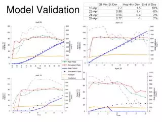
November 2003 RMS Delay Spread • Mean and standard deviation of RMS delay spreads in measurements • RMS delay spreads in the models • Model C: 30 ns small office • Model D: 50 ns typical office • Model E: 100 ns large office Q. Li (Intel), V. Erceg (Zyray), N. Tal (Metalink)
November 2003 1x1 and 4x4 Channel Capacity • SNR 15 dB; 5.2 GHz band; 20 MHz bandwidth; 4’’ spacing • CDF of 1x1 and 4x4 capacity Q. Li (Intel), V. Erceg (Zyray), N. Tal (Metalink)
November 2003 Capacity of 4x4 Channels in 5.2 GHz Band • 4x4 channel with 20 MHz bandwidth and 4’’ spacing • SNR 15dB • Model error is less than 5% Q. Li (Intel), V. Erceg (Zyray), N. Tal (Metalink)
November 2003 Capacity of 4x4 Channels in 2.4 GHz Band • 4x4 channel with 20 MHz bandwidth and 2’’ spacing • SNR 15dB • Model error is less than 15% Q. Li (Intel), V. Erceg (Zyray), N. Tal (Metalink)
November 2003 MIMO Multiplier in 5.2 GHz Band • 1x1 and 4x4 channels with 20 MHz bandwidth • SNR 15dB • MIMO multiplier is about 3.6 • Models match measurements for both 1x1 and 4x4 channels Q. Li (Intel), V. Erceg (Zyray), N. Tal (Metalink)
November 2003 MIMO Multiplier in 2.4 GHz Band • 1x1 and 4x4 channels with 20 MHz bandwidth • SNR 15dB • MIMO multiplier is about 3.3 • Models match measurements for 1x1 and 4x4 channels • Model C slightly underestimates 4x4 capacity Q. Li (Intel), V. Erceg (Zyray), N. Tal (Metalink)
November 2003 Measured K Factors • K factor is less than 0 dB in measured channels • LOS component is not dominant • D. Cheung, C. Prettie, Q. Li, and J. Lung, “Ricean K factor in office cubicle environment” IEEE doc: 802.11-03/xxxr0, Nov. 2003. Q. Li (Intel), V. Erceg (Zyray), N. Tal (Metalink)
November 2003 Summary of Intel’s Validation • Channel capacities of three office models (C,D,E) match measurements for 2.4 GHz band, 5.2 GHz band, and 2 antenna spacings • Measured delay spreads match measurements • 4x4 capacity is 3.6 and 3.3 times of 1x1 capacity for 2λ and λ/2 spacing respectively • K factor is small in the office environment Q. Li (Intel), V. Erceg (Zyray), N. Tal (Metalink)
Zyray’s Measurements • Large indoor environments (office, cafeteria) - Mainly Models D and E equivalent, partially F (only LOS). • 5.25 GHz frequency • 4x4 MIMO measurements • Dipole antennas • Antenna spacing: l/2 • LOS and NLOS conditions, 1 – 50 m • 500 MIMO channel snapshots at each location over 2.5 m distance (10 sec. measurement), 40 locations Q. Li (Intel), V. Erceg (Zyray), N. Tal (Metalink)
K-factor Experimental Data ResultsLOS, d=23.5m High K-factor on the first tap Q. Li (Intel), V. Erceg (Zyray), N. Tal (Metalink)
K-factor Experimental Data ResultsLOS, d=43.5m High K-factor on the first tap Q. Li (Intel), V. Erceg (Zyray), N. Tal (Metalink)
K-factor Experimental Data ResultsNLOS, d=16.8m Generally no high K-factors Q. Li (Intel), V. Erceg (Zyray), N. Tal (Metalink)
4 x 4 MIMO Capacity ResultsLOS Parameters: SNR = 10 dB Antennas: Dipole Antenna spacing: l/2 Capacity is approx. 70% of iid capacity Q. Li (Intel), V. Erceg (Zyray), N. Tal (Metalink)
4 x 4 MIMO Capacity ResultsNLOS Parameters: SNR = 10 dB Antennas: Dipole Antenna spacing: l/2 Capacity is approx. 80% of iid capacity Q. Li (Intel), V. Erceg (Zyray), N. Tal (Metalink)
Summary of Zyray’s Validation For the Models D and E and partially F (only LOS) equivalent environments following was found from the experimental data: • LOS K-factor is in the range 2-10 dB • NLOS K-factor is < - 2 dB in most cases • LOS 4x4 MIMO capacity is approx. 70% of iid • NLOS 4x4 MIMO capacity is approx. 80% of iid The results match proposed models well. Q. Li (Intel), V. Erceg (Zyray), N. Tal (Metalink)
Metalink’s Measurements • Several hundred of measurements taken at various locations and scenartios within the company. • Measurements were taken at the lower UNII band (~5.2 GHz) • Receive antennas fixed at a height of ~2m (e.g. AP position) • TX setup moves between measurement positions Q. Li (Intel), V. Erceg (Zyray), N. Tal (Metalink)
Measurement Set Up • Philosophy: • Full simultaneous MIMO measurements • Relatively slow sampling rate (46MHz)– long sampling period (100msec) • Store all samples and post-process offline • Use wideband transmission signals (>20MHz) • Omni reception and transmission antennas Q. Li (Intel), V. Erceg (Zyray), N. Tal (Metalink)
Indoor Measurement Locations Q. Li (Intel), V. Erceg (Zyray), N. Tal (Metalink)
Real-Environment Calculated Capacity (M11-14) (MIMO Capacity)/2 Q. Li (Intel), V. Erceg (Zyray), N. Tal (Metalink)
MIMO Capacity Enhancement- NLOS, Dist= 25.6m (M11-XX) Q. Li (Intel), V. Erceg (Zyray), N. Tal (Metalink)
MIMO Capacity Enhancement- LOS, Dist=25m (M11-XX) Q. Li (Intel), V. Erceg (Zyray), N. Tal (Metalink)
Periodic Modulation • In nearly all tests, a strong AM-like periodicity is clearly seen. • The period of this modulation was tested to be exactly 100Hz Q. Li (Intel), V. Erceg (Zyray), N. Tal (Metalink)
The Fluorescent Effect • Fluorescent lights become conductive twice every AC power cycle. • During that period, the electromagnetic environment (reflections) are changed. • The channels in such environment exhibit strong AM modulation in all parameters (frequency response, RMS delay spread, capacity, etc.) • We therefore suggest to incorporate this effect into the MIMO channel models as it is one of the major causes of channel time variability Q. Li (Intel), V. Erceg (Zyray), N. Tal (Metalink)
Summary of Metalink’s Validation • In typical enterprise scenario 2 antenna MIMO enhances the median capacity by 1.5-2x (NLOS and LOS) • Channels exhibits “slow” variability changes over 100ms (f<10Hz) • In the vicinity of fluorescence lights the channel is modulated by a strong 100/120Hz AM modulation (up to 5dB) • These results are already integrated into the channel models Q. Li (Intel), V. Erceg (Zyray), N. Tal (Metalink)
Conclusion • Validation covers model C, D, E, and F • 1x1, 2x2, and 4x4 channel capacity match measurements on both 2.4 and 5.2 GHz • Model K factors match measurements • Time variation due to fluorescent lights are included in the models • MIMO multipliers are about 1.8 and 3.5 for 2x2 and 4x4 channels respectively Q. Li (Intel), V. Erceg (Zyray), N. Tal (Metalink)
November 2003 References • [1] V. Erceg, et al, “Indoor MIMO WLAN Channel Models,” IEEE Doc. No. 802.11-03/161r2, Sept. 2003. • [2] N. Tal, “Time Variable HT MIMO Channel Measurements,” IEEE 802.11-03/515r0, July 2003. • [3] A. Jagannatham, V. Erceg, “Indoor MIMO Wireless Channel Measurements and Modeling at 5.25 GHz,” Document in preparation, Sept. 2003. • [4] D. Cheung, C. Prettie, Q. Li, and J. Lung, “Ricean K factor in office cubicle environment” IEEE doc: 802.11-03/xxxr0, Nov. 2003. • [5] – Branka Vucetic, “Space-Time Coding”, Wiley& Sons, 2003 Q. Li (Intel), V. Erceg (Zyray), N. Tal (Metalink)