Download
1 / 17
170 likes | 286 Views
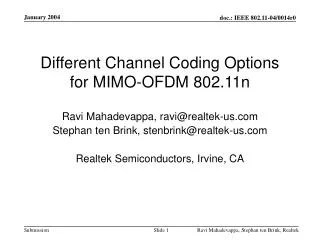
Co-Channel Inteference in 802.11n Networks. S. Aon Mujtaba, Xiaowen Wang Agere Systems. “Moore’s Law” for 802.11 Throughput Enhancement. Max PHY Layer Point-to-Point Throughput. 250Mbps?. 54Mbps. ~5x. 11Mbps. 4.9x. 2Mbps. 5.5x. 1G. 2G. 3G. 4G. Options for Throughput Enchancement.

E N D
Co-Channel Inteference in 802.11n Networks S. Aon Mujtaba, Xiaowen Wang Agere Systems
“Moore’s Law” for 802.11 Throughput Enhancement Max PHY Layer Point-to-Point Throughput 250Mbps? 54Mbps ~5x 11Mbps 4.9x 2Mbps 5.5x 1G 2G 3G 4G
Options for Throughput Enchancement • assume that 802.11n is based on an evolution of 802.11a
Target a max PHY throughput greater than 200Mbps Constrain BW to 20MHz introduce 4 transmit antennas for spatial multiplexing Assume 4 receive antennas 64QAM, R=3/4, GI=0.8us, 64-point FFT Achieve: 216Mbps System A: “4x4x20” Target a max PHY throughput greater than 200Mbps Enhance BW to 40MHz introduce 2 transmit antennas for spatial multiplexing Assume 2 receive antennas 64-QAM, R=3/4, GI=0.8us, 64-point FFT Achieve: 243Mbps System B: “2x2x40” Let’s consider two System Architectures System A System B
Link Level Simulation Setup • Channel Model = exponentially decaying power delay profile • RMS delays spreads of 50ns, 100ns, 150ns • Uncorrelated antennas • Constellation size = 64-QAM • R=3/4 (.11a encoding, puncturing, and interleaving) • Same transmit power for System A and System B • Signal PSD for 40MHz is ½ that of 20MHz • Frequency offset = 100kHz • No phase noise impairment • 1000 Byte packets • Spatial Multiplexing (no transmitter pre-coding) • Soft-output Zero-Forcing Receiver
Simulation Results (50ns RMS delay spread) 26 28 30 32 34 36 38 1 0.1 4x4x20MHz PER 2x2x40MHz 5dB 0.01 0.001 SNR (dB)
Simulation Results (100ns RMS delay spread) 26 28 30 32 34 36 38 1 4x4x20MHz 0.1 PER 2x2x40MHz 0.01 SNR 4dB
Simulation Results (150ns RMS Delay Spread) 28 30 32 34 36 38 40 42 1 4x4x20MHz PER 0.1 2x2x40MHz 0.01 SNR (dB)
Observations • The 4x4 system has more self-interference than the 2x2 system • Hence, the need for higher SNR for decoding purposes • Increasing the BW from 20 to 40MHz does not degrade Eb/No: • Both data rate and BW increase by roughly 2x • However, SNR does reduce by 3dB for same transmit power • 4x4 systems is very sensitive to ICI hence, the 4x4 system fails at 150ns RMS delay spread • As the RMS delay spread increases from 50ns to 100ns, the benefit of 40MHz BW reduces by 1dB (at 1% PER)
Comments • In an isolated cell, a 2x2x40 system requires less decoding SNR than a 4x4x20 system • However, increasing the bandwidth reduces the number of channels available for frequency re-use • possibility for higher co-channel interference
Reuse=1/7 in 5GHz (BW=20MHz) With 20MHz channelization, there are sufficient number of channels available in 5GHz to achieve the classical 1/7 reuse pattern, as shown: 2 2 7 3 Number of interferers in the 1st ring = 6 7 3 1 1 6 4 6 4 5 5 d
Reuse=1/4 in 5GHz (BW=40MHz) With 40MHz channelization, let’s assume that the number of usable channels in 5GHz drops to 4. 4 4 Number of interferers in the 1st ring = 8 2 2 1 1 3 3 d
Modeling assumptions for calculating CCI • While co-channel interference (CCI) affects the entire cell, for sake of simplicity, we only consider the interference from Access Point to Access Point. • We assume that all Access Points transmit the same power • In going from 20MHz to 40MHz operation, we assume that the radius of the cells does not have to change since the SNR requried for 6Mbps reception is the same for System A and B. I(r) r CCI AP AP STA
Translating distance to CCI Power Level 20dB/decade 16dBm Free Space 33dB/decade Break Point r I(r) AP CCI AP
Conclusions • In an isolated cell, bandwidth expansion coupled with spatial multiplexing provides a more robust path to throughput enhancement • 2x2x40MHz is ~5dB more robust than 4x4x20MHz at 1% PER • In a multi-cellular deployment: • BW expansion increases Co-Channel interference • SNR degradation due to CCI increase is balanced out by increase in link robustness • “comparable” capacity of 2x2x40 and 4x4x20 systems