Download
1 / 56
560 likes | 565 Views
ELEC 5270/6270 Spring 2009 Low-Power Design of Electronic Circuits Gate-Level Power Analysis. Vishwani D. Agrawal James J. Danaher Professor Dept. of Electrical and Computer Engineering Auburn University, Auburn, AL 36849 vagrawal@eng.auburn.edu

E N D
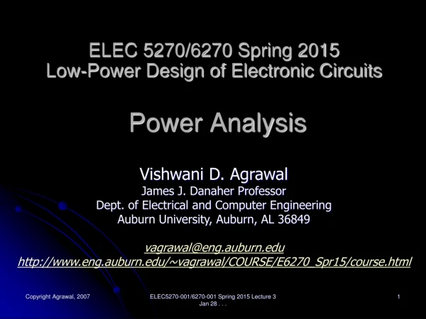
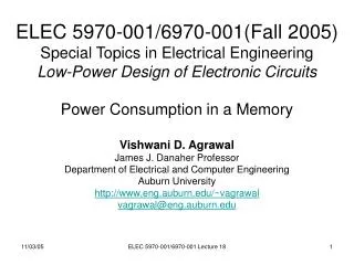
ELEC 5270/6270 Spring 2009Low-Power Design of Electronic CircuitsGate-Level Power Analysis Vishwani D. Agrawal James J. Danaher Professor Dept. of Electrical and Computer Engineering Auburn University, Auburn, AL 36849 vagrawal@eng.auburn.edu http://www.eng.auburn.edu/~vagrawal/COURSE/E6270_Spr09/course.html ELEC5270-001/6270-001Spr 09, Lecture 5
Power Analysis • Motivation: • Specification • Optimization • Reliability • Applications • Design analysis and optimization • Physical design • Packaging • Test ELEC5270-001/6270-001Spr 09, Lecture 5
Abstraction, Complexity, Accuracy ELEC5270-001/6270-001Spr 09, Lecture 5
Spice • Circuit/device level analysis • Circuit modeled as network of transistors, capacitors, resistors and voltage/current sources. • Node current equations using Kirchhoff’s current law. • Average and instantaneous power computed from supply voltage and device current. • Analysis is accurate but expensive • Used to characterize parts of a larger circuit. • Original references: • L. W. Nagel and D. O. Pederson, “SPICE – Simulation Program With Integrated Circuit Emphasis,” Memo ERL-M382, EECS Dept., University of California, Berkeley, Apr. 1973. • L. W. Nagel, SPICE 2, A Computer program to Simulate Semiconductor Circuits, PhD Dissertation, University of California, Berkeley, May 1975. ELEC5270-001/6270-001Spr 09, Lecture 5
Ca Logic Model of MOS Circuit VDD pMOS FETs a Da c Dc a b Db c Cc b Daand Dbare interconnect or propagation delays Dcis inertial delay of gate Cb nMOS FETs Cd Ca , Cb , Cc and Cd are node capacitances ELEC5270-001/6270-001Spr 09, Lecture 5
Spice Characterization of a 2-Input NAND Gate ELEC5270-001/6270-001Spr 09, Lecture 5
Spice Characterization (Cont.) ELEC5270-001/6270-001Spr 09, Lecture 5
Switch-Level Partitioning • Circuit partitioned into channel-connected components for Spice characterization. • Reference: R. E. Bryant, “A Switch-Level Model and Simulator for MOS Digital Systems,” IEEE Trans. Computers, vol. C-33, no. 2, pp. 160-177, Feb. 1984. G2 Internal switching nodes not seen by logic simulator G3 G1 ELEC5270-001/6270-001Spr 09, Lecture 5
Delay and Discrete-Event Simulation(NAND gate) Transient region a Inputs b c (CMOS) c (zero delay) c (unit delay) Logic simulation X rise=5, fall=5 c (multiple delay) Unknown (X) c (minmax delay) min =2, max =5 5 Time units 0 ELEC5270-001/6270-001Spr 09, Lecture 5
Event-Driven Simulation Example Activity list d, e f, g g Scheduled events c = 0 d = 1, e = 0 g = 0 f = 1 g = 1 a =1 e =1 t = 0 1 2 3 4 5 6 7 8 2 c =1→0 g =1 2 2 d = 0 Time stack 4 f =0 b =1 g 8 4 0 Time, t ELEC5270-001/6270-001Spr 09, Lecture 5
Time Wheel (Circular Stack) max Current time pointer t=0 Event link-list 1 2 3 4 5 6 7 ELEC5270-001/6270-001Spr 09, Lecture 5
Gate-Level Power Analysis • Pre-simulation analysis: • Partition circuit into channel connected gate components. • Determine node capacitances from layout analysis (accurate) or from wire-load model* (approximate). • Determine dynamic and static power from Spice for each gate. • Determine gate delays using Spice or Elmore delay model. * Wire-load model estimates capacitance of a net by its pin-count. See Yeap, p. 39. ELEC5270-001/6270-001Spr 09, Lecture 5
Elmore Delay Model • W. Elmore, “The Transient Response of Damped Linear Networks with Particular Regard to Wideband Amplifiers,” J. Appl. Phys., vol. 19, no.1, pp. 55-63, Jan. 1948. 2 R2 C2 1 R1 s 4 R4 C4 C1 R3 3 R5 Shared resistance: R45 = R1 + R3 R15 = R1 R34 = R1 + R3 C3 5 C5 ELEC5270-001/6270-001Spr 09, Lecture 5
Elmore Delay Formula N Delay at node k = 0.69 ΣCj × Rjk j=1 where N = number of capacitive nodes in the network Example: Delay at node 5 = 0.69[R1 C1 + R1 C2 + (R1+R3)C3 + (R1+R3)C4 + (R1+R3+R5)C5] ELEC5270-001/6270-001Spr 09, Lecture 5
Gate-Level Power Analysis (Cont.) • Run discrete-event (event-driven) logic simulation with a set of input vectors. • Monitor the toggle count of each net and obtain capacitive component of power dissipation: Pcap=ΣCk V 2f all nodes k • Where: • Ckis the total node capacitance being switched, as determined by the simulator. • V is the supply voltage. • f is the clock frequency, i.e., the number of vectors applied per unit time ELEC5270-001/6270-001Spr 09, Lecture 5
Gate-Level Power Analysis (Cont.) • Monitor dynamic energy events at the input of each gate and obtain internal switching (short circuit) power dissipation: Pint = ΣΣ E(g,e) F(g,e) gates g events e • Where • E(g,e) = energy of event e of gate g, pre-computed short-circuit power from Spice. • F(g,e) = occurrence frequency of the event e at gate g, observed by logic simulation. ELEC5270-001/6270-001Spr 09, Lecture 5
Gate-Level Power Analysis (Cont.) • Monitor the static power dissipation state of each gate and obtain the static power dissipation: Pstat = ΣΣP(g,s) T(g,s)/ T gates g states s • Where • P(g,s) = static power dissipation of gate g for state s, obtained from Spice. • T(g,s) = duration of state s at gate g, obtained from logic simulation. • T = number of vectors × vector period. ELEC5270-001/6270-001Spr 09, Lecture 5
Gate-Level Power Analysis • Sum up all three components of power: P = Pcap + Pint + Pstat • References: • A. Deng, “Power Analysis for CMOS/BiCMOS Circuits,” Proc. International Workshop Low Power Design, 1994. • J. Benkoski, A. C. Deng, C. X. Huang, S. Napper and J. Tuan, “Simulation Algorithms, Power Estimation and Diagnostics in PowerMill,” Proc. PATMOS, 1995. • C. X. Huang, B. Zhang, A. C. Deng and B. Swirski, “The Design and Implementation of PowerMill,” Proc. International Symp. Low Power Design, 1995, pp. 105-109. ELEC5270-001/6270-001Spr 09, Lecture 5
Probabilistic Analysis • View signals as a random processes Prob{s(t) = 1} = p1 p0 = 1 – p1 C 0→1 transition probability = (1 – p1) p1 Power, P = (1 – p1) p1 CV 2 fck ELEC5270-001/6270-001Spr 09, Lecture 5
Source of Inaccuracy p1 = 0.5 P = 0.5CV 2 fck 1/fck p1 = 0.5 P = 0.33CV 2 fck p1 = 0.5 P = 0.167CV 2 fck Observe that the formula, Power, P = (1 – p1) p1 C V 2 fck= 0.25 C V 2 fckis not correct. ELEC5270-001/6270-001Spr 09, Lecture 5
Switching Frequency Number of transitions per unit time: N(t) T = ─── t For a continuous signal: N(t) T = lim ─── t→∞ t T is defined as transition density. ELEC5270-001/6270-001Spr 09, Lecture 5
Static Signal Probabilities • Observe signal for interval t 0 + t 1 • Signal is 1 for duration t 1 • Signal is 0 for duration t 0 • Signal probabilities: • p 1 = t 1/(t 0 + t 1) • p 0 = t 0/(t 0 + t 1) = 1 – p 1 ELEC5270-001/6270-001Spr 09, Lecture 5
Static Transition Probabilities • Transition probabilities: • T 01 = p 0 Prob{signal is 1 | signal was 0} = p 0 p1 • T 10 = p 1 Prob{signal is 0 | signal was 1} = p 1 p 0 • T = T 01 + T 10 = 2 p 0 p 1 = 2 p 1 (1 – p 1) ELEC5270-001/6270-001Spr 09, Lecture 5
Static Transition Probability 0.25 0.2 0.1 0.0 f = p1(1 – p1) 0 0.25 0.5 0.75 1.0 p1 ELEC5270-001/6270-001Spr 09, Lecture 5
Inaccuracy in Transition Probability p1 = 0.5 T = 1.0 1/fck p1 = 0.5 T = 4/6 p1 = 0.5 T = 1/6 Observe that the formula, T = 2 p1 (1 – p1), is not correct. ELEC5270-001/6270-001Spr 09, Lecture 5
Cause for Error and Correction • Probability of transition is not independent of the present state of the signal. • Determine probability p 01 of a 0→1 transition. • Recognize p 01 ≠ p 0 × p 1 • We obtain p 1 = (1 – p 1) p 01 + p 1 p 11 p 01 p 1 = ───────── 1 – p 11 + p 01 ELEC5270-001/6270-001Spr 09, Lecture 5
Correction (Cont.) • Since p 11 + p 10 = 1, i.e., given that the signal was previously 1, its present value can be either 1 or 0. • Therefore, p 01 p 1 = ────── p 10 + p 01 This uniquely gives signal probability as a function of transition probabilities. ELEC5270-001/6270-001Spr 09, Lecture 5
Transition and Signal Probabilities p01 = p10 = 1.0 p00 = p11 = 0.0 p1= 0.5 1/fck p01 = p10 = 2/3 p00 = p11 = 1/3 p1= 0.5 p01 = p10 = 1/4 p01 = p10 = 3/4 p1= 0.5 ELEC5270-001/6270-001Spr 09, Lecture 5
Probabilities: p0, p1, p00, p01, p10, p11 • p 01 + p 00 = 1 • p 11 + p 10 = 1 • p 0 = 1 – p 1 p 01 p 1 = ─────── p 10 + p 01 ELEC5270-001/6270-001Spr 09, Lecture 5
Transition Density • T = 2 p 1 (1 – p 1) = p 0 p 01 + p 1 p 10 = 2 p 10 p 01 / (p 10 + p 01) = 2 p 1 p 10 = 2 p 0 p 01 ELEC5270-001/6270-001Spr 09, Lecture 5
Power Calculation • Power can be estimated if transition density is known for all signals. • Calculation of transition density requires • Signal probabilities • Transition densities for primary inputs; computed from vector statistics ELEC5270-001/6270-001Spr 09, Lecture 5
Signal Probabilities x1 x2 x1 x2 x1 x2 x1 + x2 – x1x2 1 - x1 x1 ELEC5270-001/6270-001Spr 09, Lecture 5
Signal Probabilities 0.5 x1 x2 x3 x1 x2 0.25 0.5 0.625 0.5 y = 1 - (1 - x1x2) x3 = 1 - x3 + x1x2x3 = 0.625 X1 X2 X3 Y 0 0 0 1 0 0 1 0 0 1 0 1 0 1 1 0 1 0 0 1 1 0 1 0 1 1 0 1 1 1 1 1 Ref: K. P. Parker and E. J. McCluskey, “Probabilistic Treatment of General Combinational Networks,” IEEE Trans. on Computers, vol. C-24, no. 6, pp. 668-670, June 1975. ELEC5270-001/6270-001Spr 09, Lecture 5
Correlated Signal Probabilities 0.5 x1 x2 x1 x2 0.5 0.25 0.625? y = 1 - (1 - x1x2) x2 = 1 – x2 + x1x2x2 = 1 – x2 + x1x2 = 0.75 (correct value) X1 X2 Y 0 0 1 0 1 0 1 0 1 1 1 1 ELEC5270-001/6270-001Spr 09, Lecture 5
Correlated Signal Probabilities 0.5 x1 + x2 – x1x2 x1 x2 0.75 0.5 0.375? y = (x1 + x2 – x1x2) x2 = x1x2 + x2x2 – x1x2x2 = x1x2 + x2 – x1x2 = x2 = 0.5 (correct value) X1 X2Y 0 0 0 0 1 1 1 0 0 1 1 1 ELEC5270-001/6270-001Spr 09, Lecture 5
Observation • Numerical computation of signal probabilities is accurate for fanout-free circuits. ELEC5270-001/6270-001Spr 09, Lecture 5
Remedies • Use Shannon’s expansion theorem to compute signal probabilities. • Use Boolean difference formula to compute transition densities. ELEC5270-001/6270-001Spr 09, Lecture 5
Shannon’s Expansion Theorem • C. E. Shannon, “A Symbolic Analysis of Relay and Switching Circuits,” Trans. AIEE, vol. 57, pp. 713-723, 1938. • Consider: • Boolean variables, X1, X2, . . . , Xn • Boolean function, F(X1, X2, . . . , Xn) • Then F = Xi F(Xi=1) + Xi’ F(Xi=0) • Where • Xi’ is complement of X1 • Cofactors, F(Xi=j) = F(X1, X2, . . , Xi=j, . . , Xn), j = 0 or 1 ELEC5270-001/6270-001Spr 09, Lecture 5
Expansion About Two Inputs • F = XiXj F(Xi=1, Xj=1) + XiXj’ F(Xi=1, Xj=0) + Xi’Xj F(Xi=0, Xj=1) + Xi’Xj’ F(Xi=0, Xj=0) • In general, a Boolean function can be expanded about any number of input variables. • Expansion about k variables will have 2k terms. ELEC5270-001/6270-001Spr 09, Lecture 5
Correlated Signal Probabilities X1 X2 X1 X2 Y = X1 X2 + X2’ X1 X2 Y 0 0 1 0 1 0 1 0 1 1 1 1 Shannon expansion about the reconverging input, X2: Y = X2 Y(X2 = 1) + X2’ Y(X2 = 0) = X2 (X1) + X2’ (1) ELEC5270-001/6270-001Spr 09, Lecture 5
Correlated Signals • When the output function is expanded about all reconverging input variables, • All cofactors correspond to fanout-free circuits. • Signal probabilities for cofactor outputs can be calculated without error. • A weighted sum of cofactor probabilities gives the correct probability of the output. • For two reconverging inputs: f = xixj f(Xi=1, Xj=1) + xi(1-xj) f(Xi=1, Xj=0) + (1-xi)xj f(Xi=0, Xj=1) + (1-xi)(1-xj) f(Xi=0, Xj=0) ELEC5270-001/6270-001Spr 09, Lecture 5
Correlated Signal Probabilities X1 X2 X1 X2 Y = X1 X2 + X2’ X1 X2 Y 0 0 1 0 1 0 1 0 1 1 1 1 Shannon expansion about the reconverging input, X2: Y = X2 Y(X2=1) + X2’ Y(X2=0) = X2 (X1) + X2’ (1) y = x2 (0.5) + (1-x2) (1) = 0.5 (0.5) + (1-0.5) (1) = 0.75 ELEC5270-001/6270-001Spr 09, Lecture 5
Example 0.5 Supergate 0.25 Point of reconv. 0.5 0.0 0.5 1.0 0.5 1 0 0.0 1.0 0.5 0.375 0.5 Reconv. signal Signal probability for supergate output = 0.5 Prob{rec. signal = 1} + 1.0 Prob{rec. signal = 0} = 0.5 × 0.5 + 1.0 × 0.5 = 0.75 S. C. Seth and V. D. Agrawal, “A New Model for Computation of Probabilistic Testability in Combinational Circuits,” Integration, the VLSI Journal, vol. 7, no. 1, pp. 49-75, April 1989. ELEC5270-001/6270-001Spr 09, Lecture 5
Probability Calculation Algorithm • Partition circuit into supergates. • Definition: A supergate is a circuit partition with a single output such that all fanouts that reconverge at the output are contained within the supergate. • Identify reconverging and non-reconverging inputs of each supergate. • Compute signal probabilities from PI to PO: • For a supergate whose input probabilities are known • Enumerate reconverging input states • For each input state do gate by gate probability computation • Sum up corresponding signal probabilities, weighted by state probabilities ELEC5270-001/6270-001Spr 09, Lecture 5
Calculating Transition Density 1 Boolean function x1, T1 . . . . . xn, Tn y, T(Y) = ? n ELEC5270-001/6270-001Spr 09, Lecture 5
Boolean Difference ∂Y Boolean diff(Y, Xi) = ── = Y(Xi=1) ⊕ Y(Xi=0) ∂Xi • Boolean diff(Y, Xi) = 1 means that a path is sensitized from input Xi to output Y. • Prob(Boolean diff(Y, Xi) = 1) is the probability of transmitting a toggle from Xi to Y. • Probability of Boolean difference is determined from the probabilities of cofactors of Y with respect to Xi. F. F. Sellers, M. Y. Hsiao and L. W. Bearnson, “Analyzing Errors with the Boolean Difference,” IEEE Trans. on Computers, vol. C-17, no. 7, pp. 676-683, July 1968. ELEC5270-001/6270-001Spr 09, Lecture 5
Transition Density n T(y) = Σ T(Xi) Prob(Boolean diff(Y, Xi) = 1) i=1 F. Najm, “Transition Density: A New Measure of Activity in Digital Circuits,” IEEE Trans. CAD, vol. 12, pp. 310-323, Feb. 1993. ELEC5270-001/6270-001Spr 09, Lecture 5
Power Computation • For each primary input, determine signal probability and transition density for given vectors. • For each internal node and primary output Y, find the transition density T(Y), using supergate partitioning and the Boolean difference formula. • Compute power, P = Σ 0.5CY V2 T(Y) all Y where CY is the capacitance of node Y and V is supply voltage. ELEC5270-001/6270-001Spr 09, Lecture 5
Transition Density and Power 0.2, 1 X1 X2 X3 0.06, 0.7 0.3, 2 0.436, 3.24 Ci Y CY 0.4, 3 Transition density Signal probability Power = 0.5 V 2 (0.7Ci + 3.24CY) ELEC5270-001/6270-001Spr 09, Lecture 5
Prob. Method vs. Logic Sim. * CONVEX c240 ELEC5270-001/6270-001Spr 09, Lecture 5