Download
1 / 79

E N D
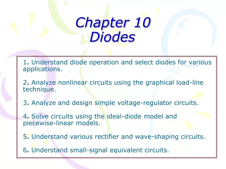
Chapter 10 Diodes1. Understand diode operation and select diodes for various applications.2. Analyze nonlinear circuits using the graphical load-line technique.3. Analyze and design simple voltage-regulator circuits.4. Solve circuits using the ideal-diode model andpiecewise-linear models.5. Understand various rectifier and wave-shaping circuits.6. Understand small-signal equivalent circuits.
10. Diodes – Basic Diode Concepts 10.1 Basic Diode Concepts 10.1.1 Intrinsic Semiconductors * Energy Diagrams – Insulator, Semiconductor, and Conductor the energy diagram for the three types of solids
10. Diodes – Basic Diode Concepts 10.1.1 Intrinsic Semiconductors * Intrinsic (pure) Si Semiconductor: Thermal Excitation, Electron-Hole Pair, Recombination, and Equilibrium
10. Diodes – Basic Diode Concepts 10.1.1 Intrinsic Semiconductors *Apply a voltage across a piece of Si: electron current and hole current
10. Diodes – Basic Diode Concepts 10.1.2 N- and P- Type Semiconductors * Doping: adding of impurities (i.e., dopants) to the intrinsic semi-conductor material. * N-type: adding Group V dopant (or donor) such as As, P, Sb,…
10. Diodes – Basic Diode Concepts 10.1.2 N- and P- Type Semiconductors * Doping: adding of impurities (i.e., dopants) to the intrinsic semi-conductor material. * P-type: adding Group III dopant (or acceptor) such as Al, B, Ga,…
10. Diodes – Basic Diode Concepts 10.1.3 The PN-Junction * The interface in-between p-type and n-type material is called a pn-junction.
10. Diodes – Basic Diode Concepts 10.1.4 Biasing the PN-Junction * There is no movement of charge through a pn-junction at equilibrium. * The pn-junction form a diode which allows current in only one direction and prevent the current in the other direction as determined by the bias.
10. Diodes – Basic Diode Concepts 10.1.4 Biasing the PN-Junction *Forward Bias: dc voltage positive terminal connected to the p region and negative to the n region. It is the condition that permits current through the pn-junction of a diode.
10.1.4 Biasing the PN-Junction *Forward Bias: dc voltage positive terminal connected to the p region and negative to the n region. It is the condition that permits current through the pn-junction of a diode.
10. Diodes – Basic Diode Concepts 10.1.4 Biasing the PN-Junction *Forward Bias:
10. Diodes – Basic Diode Concepts *Reverse Bias: dc voltage negative terminal connected to the p region and positive to the n region. Depletion region widens until its potential difference equals the bias voltage, majority-carrier current ceases.
10. Diodes – Basic Diode Concepts *Reverse Bias: majority-carrier current ceases. * However, there is still a very small current produced by minority carriers.
10. Diodes – Basic Diode Concepts 10.1.4 Biasing the PN-Junction * Reverse Breakdown: As reverse voltage reach certain value, avalanche occurs and generates large current.
10. Diodes – Basic Diode Concepts 10.1.5 The Diode Characteristic I-V Curve
10. Diodes – Basic Diode Concepts 10.1.6 Shockley Equation * The Shockley equation is a theoretical result under certain simplification:
10. Diodes – Load-Line Analysis of Diode Circuits 10.2 Load-Line Analysis of Diode Circuit
10. Diodes – Load-Line Analysis of Diode Circuits Example 10.1- Load-Line Analysis
10. Diodes – Load-Line Analysis of Diode Circuits Example 10.2 - Load-Line Analysis
10. Diodes – Zener Diode Voltage-Regulator Circuits 10.3 Zener-Diode Voltage-Regulator Circuits 10.3.1 The Zener Diode * Zener diode is designed for operation in the reverse-breakdown region. * The breakdown voltage is controlled by the doping level (-1.8 V to -200 V). * The major application of Zener diode is to provide an output reference that is stable despite changes in input voltage – power supplies, voltmeter,…
10. Diodes – Zener-Diode Voltage-Regulator Circuits 10.3.2 Zener-Diode Voltage-Regulator Circuits * Sometimes, a circuit that produces constant output voltage while operating from a variable supply voltage is needed. Such circuits are called voltage regulator. * The Zener diode has a breakdown voltage equal to the desired output voltage. * The resistor limits the diode current to a safe value so that Zener diode does not overheat.
10. Diodes – Zener-Diode Voltage-Regulator Circuits Example 10.3 – Zener-Diode Voltage-Regulator Circuits Actual Zener diode performs much better!
10. Diodes – Zener-Diode Voltage-Regulator Circuits 10.3.3 Load-Line Analysis of Complex Circuits * Use the Thevenin Equivalent
10. Diodes – Zener-Diode Voltage-Regulator Circuits Example 10.4 – Zener-Diode Voltage-Regulator with a Load
10. Diodes – Zener-Diode Voltage-Regulator Circuits Quiz – Exercise 10.5
10. Diodes – Ideal-Diode Model 10.4 Ideal-Diode Model * Graphical load-line analysis is too cumbersome for complex circuits, * We may apply “Ideal-Diode Model” to simplify the analysis: (1) in forward direction: short-circuit assumption, zero voltage drop; (2) in reverse direction: open-circuit assumption. * The ideal-diode model can be used when the forward voltage drop and reverse currents are negligible.
10. Diodes – Ideal-Diode Model 10.4 Ideal-Diode Model * In analysis of a circuit containing diodes, we may not know in advance which diodes are on and which are off. * What we do is first to make a guess on the state of the diodes in the circuit:
10. Diodes – Ideal-Diode Model Example 10.5 – Analysis by Assumed Diode States
10. Diodes – Ideal-Diode Model Quiz – Exercise 10.8c * Find the diode states by using ideal-diode model. Starting by assuming both diodes are on.
10. Diodes – Piecewise-Linear Diode Models 10.5 Piecewise-Linear Diode Models 10.5.1 Modified Ideal-Diode Model * This modified ideal-diode model is usually accurate enough in most of the circuit analysis.
10. Diodes – Piecewise-Linear Diode Models 10.5.2 Piecewise-Linear Diode Models
10. Diodes – Rectifier Circuits 10.6 Rectifier Circuits * Rectifiers convert ac power to dc power. * Rectifiers form the basis for electronic power suppliers and battery charging circuits. 10.6.1 Half-Wave Rectifier
10. Diodes – Rectifier Circuits * Battery-Charging Circuit * The current flows only in the direction that charges the battery.
10. Diodes – Rectifier Circuits * Half-Wave Rectifier with Smoothing Capacitor * To place a large capacitance across the output terminals:
10. Diodes – Rectifier Circuits 10.6.2 Full-Wave Rectifier Circuits * Center-Tapped Full-Wave Rectifier – two half-wave rectifier with out-of-phase source voltages and a common ground. * When upper source supplies “+” voltage to diode A, the lower source supplies “-” voltage to diode B; and vice versa. * We can also smooth the output by using a large capacitance.
10. Diodes – Rectifier Circuits 10.6.2 Full-Wave Rectifier Circuits * The Diode-Bridge Full-Wave Rectifier: A,B C,D
10. Diodes – Wave-Shaping Circuits 10.7 Wave-Shaping Circuits 10.7.1 Clipper Circuits * A portion of an input signal waveform is “clipped” off.
10. Diodes – Wave-Shaping Circuits 10.7 Wave-Shaping Circuits 10.7.2 Clamper Circuits * Clamp circuits are used to add a dc component to an ac input waveform so that the positive (or negative) peaks are “clamped” to a specified voltage value.
10. Diodes – Linear Small-Signal Equivalent Circuits 10.8 Linear Small-Signal Equivalent Circuits * In most of the electronic circuits, dc supply voltages are used to bias a nonlinear device at an operating point and a small signal is injected into the circuits. * We often split the analysis of such circuit into two parts: (1) Analyze the dc circuit to find operating point, (2) Analyze the small signal ( by using the “linear small- signal equivalent circuit”.)
10. Diodes – Linear Small-Signal Equivalent Circuits 10.8 Linear Small-Signal Equivalent Circuits * A diode in linear small-signal equivalent circuit is simplified to a resistor. * We first determine the operating point (or the “quiescent point” or Q point) by dc bias. * When small ac signal injects, it swings the Q point slightly up and down. * If the signal is small enough, the characteristic is straight.
10. Diodes – Linear Small-Signal Equivalent Circuits 10.8 Linear Small-Signal Equivalent Circuits
10. Diodes – Linear Small-Signal Equivalent Circuits 10.8 Linear Small-Signal Equivalent Circuits * By using these two equations, we can treat diode simply as a linear resistor in small ac signal analysis. * Note: An ac voltage of fixed amplitude produces different ac current change at different Q point.
10. Diodes – Linear Small-Signal Equivalent Circuits 10.8 Linear Small-Signal Equivalent Circuits
10. Diodes – Linear Small-Signal Equivalent Circuits Voltage-Controlled Attenuator * The function of this circuit is to produce an output signal that is a variable fraction of the ac input signal. * Two large coupling capacitors: behave like short circuit for ac signal and open circuit for dc, thus the Q point of the diode is unaffected by the ac input and the load.
10. Diodes – Linear Small-Signal Equivalent Circuits Voltage-Controlled Attenuator
10. Diodes – Linear Small-Signal Equivalent Circuits Exercise 10.20 - Voltage-Controlled Attenuator
Chapter 11: Amplifiers:Specifications and External Characteristics
11. Amplifiers – Basic Amplifier Concepts 11.1 Basic Amplifier Concepts 11.1.1 For Starting * Ideally, an amplifier produces an output signal with identical wave-shape as the input signal but with a larger amplitude.
11. Amplifiers – Basic Amplifier Concepts 11.1.1 For Starting * inverting and non-inverting amplifiers
11. Amplifiers – Basic Amplifier Concepts 11.1.1 For Starting * Often, one of the amplifier input terminals and one of the output terminals are connected to a common ground. * The common ground serve as the return path for signal and the dc power supply currents.