Download
1 / 44
460 likes | 739 Views
September 2003. doc: IEEE 802.11-03/773r1. EVM SIMULATIONS FOR OFDM EVM vs BER data plots and data tables to support PSNI premise. Joe Kwak InterDigital Communications Corporation. OUTLINE. Background for EVM Simulation Work EVM Measurement Notes Public Domain Simulation Tool

E N D
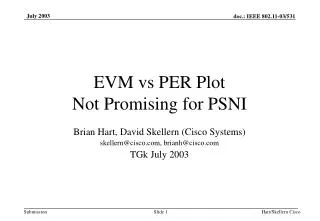
September 2003 doc: IEEE 802.11-03/773r1 EVM SIMULATIONS FOR OFDMEVM vs BER data plots and data tables to support PSNI premise Joe Kwak InterDigital Communications Corporation Joe Kwak, InterDigital
OUTLINE • Background for EVM Simulation Work • EVM Measurement Notes • Public Domain Simulation Tool • EVM Calculations in Simulator • Simulation Setup/Assumptions • Plotted Simulation Results • Importance of EVM variance in Fading Channels • Conclusions Joe Kwak, InterDigital
Background • 11-03-315r2-K-RCPI_PSNI_Measurements.ppt, presented at May meeting, proposed a single scalar measure (PSNI) as new signal quality indicator for all WLAN rates, modulations, FEC, and channel conditions. • PSNI to be based on internal demod parameter such as EVM, internal observed SNR paramter, or other param. • PSNI to be specified in AWGN for PER performance. • Validity of PSNI(or EVM) as quality indicator of BER was questioned in fading channels. • Dave Skellern and Joe Kwak agreed to study EVM. • Skellern argues EVM not valid indicator, Kwak argues EVM is adequate indicator of signal quality and BER. Joe Kwak, InterDigital
Graphical Error Vector Magnitude Error Vector: due to noise or distortion Transmitted symbol (Io,Qo) I I (Is,Qs) Q Q Average power circle EVM measure requires apriori knowledge of transmitted symbol, or must assume that closest constellation point is transmitted symbol. EVM is normalised to average power. Joe Kwak, InterDigital
EVM Calculation in Transmitter • EVM has gained popularity as a figure of merit for transmitters. • EVM may be easily computed from a modulated signal because: • SNRs are extremely high so that the measured EVM represents transmitter constellation distortion, and not noise-induced signal distortion. • High SNRs for measurement means that nearest constellation point is always the transmitted constellation point, I.e BER = 0 for transmitter testing purposes. • The same technique, widely used for transmitters and specified for 802.11 transmitters, does not directly apply to EVM measurement in receivers. Joe Kwak, InterDigital
EVM Calculation in Receiver • Characterization of receivers is not limited to high SNRs; receivers are designed for operation in very low SNRs, where link distances are stretched to maximum. • At low SNRs, processed symbol (I,Q) may cross demodulation decision boundary and lead to demod errors. • Practical measurement of EVM in receivers has no apriori knowledge of transmitted symbol and so must assume closest constellation point. • This assumption leads to EVM error in low SNR: measured EVM is lower than actual EVM; measured Inverse EVM is higher than actual IEVM. Joe Kwak, InterDigital
Inverse EVM • EVM in simulator is computed according to : ([(I-Io)2+(Q-Qo)2])1/2 --------------------------- Nsubcsym * (Im2 + Qm2)1/2 where (Io,Qo) is nearest constellation point, and (Im2 + Qm2)1/2 is the average signal power, and summation is taken over all packet subcarrier symbols. • The Inverse EVM is equivalent to SNR where, • IEVM = 20*log10( 1 / EVM ) • Plots of IEVM vs SNR in AWGN shows simulator EVM produces expected results. Joe Kwak, InterDigital
Matlab Simulation Tool • A publically available MATLAB simulation tool has been published in OFDM Wireless LANs: A Theoretical and Practical Guide, Juha Heiskala and John Terry, SAMS publishing, 2002. • This tool implements IEEE802.11a modulations and coding and uses AWGN channel or the IEEE exponentially decaying ray channel model to demonstrate WLAN capability. • This simulation tools calculates rawBER, data BER, PER on a packet by packet basis for any input SNR value and channel model using various ray decay time constants. • This tool was modified to also compute EVM average and EVM Sdev over a series of packets. Joe Kwak, InterDigital
EVM Calculation in Simulation Tool Receiver • Matlab receiver.m code module directs processing; EVM calc is performed just prior to demodulation: • Packet Detection • Frequency Error estimation and correction • Fine time synchronization • Channel estimation • Phase error estimation and correction • Rx diversity processing • Amplitude normalization • EVM calculation • Soft decision demodulation • Deinterleaving • Depuncturing • Soft decision weighting with subcarrier amps • Viterbi soft decision FEC decoding Joe Kwak, InterDigital
IEVM vs SNR in AWGN Joe Kwak, InterDigital
IEVM Error at low SNRs • When EVM is computed for transmit constellation testing, the transmitted signal is always at high SNR and the transmitted constellation point is always the nearest constellation point. • EVM computation in a receiver also assumes that nearest constellation point is intended constellation point. • This leads to EVM error at low SNR values when high noise levels may cause signal to cross demod decision boundary, leading to raw bit errors. Joe Kwak, InterDigital
EVM Error at low SNR Values Joe Kwak, InterDigital
Simulation Setup at 6Mbps (BPSK, R=1/2) • Simulator has many real-world options which were not studied or used for this effort. • Simulator is setup to provide near-ideal receiver performance, with minimal implementation-dependant losses: • Ideal packet detection • Ideal synchronization algorithms: time, freq, phase • No PA distortions • No transmitter phase noise • Adequate channel estimation algorithm (unverified) • No TX or Rx diversity • Full precision calculations, no quantization errors • Simulator tested and shows expected theoretical performance. Joe Kwak, InterDigital
Simulation Setup at 6Mbps (BPSK, R=1/2) (cont) • Each plotted simulation point consists of 1000 simulated packets with 1000 data bits per packet (10E6 bits per data point). • For each data point, the simulator calculated the IEVM mean, IEVM stddev, raw BER, data BER (after FEC decoding). • Data was collected using various channel models: AWGN, IEEE fading using 25, 50, 100, 200, and 400 nsec decay times. • For each channel model, SNR was varied for each data point from -6 to +20dB in 2 dB steps. Joe Kwak, InterDigital
IEVM vs Raw BER for AWGN and Fading Channels Joe Kwak, InterDigital
IEVM vs Data BER (after FEC decoding) Joe Kwak, InterDigital
Variance of EVM as modifier of measured EVM • The standard deviation (Sdev) is computed for all IEVMs measured in the simulations. • The Sdev varies with the decay time constant of the exponentially decaying rays in the fading model, in IEVM range from -5 to 40db • It may be useful to use the Sdev value to modify the measured IEVM to make an adjustment to more closely align the IEVMs in fading channels with that of AWGN case for better indication of Data BER. IEVM Sdev 0.10 3.59 3.91 4.55 5.33 5.94 Tdecay (nsec) AWGN 400 200 100 50 25 Joe Kwak, InterDigital
IEVMmod: Adjusted IEVM measurement • Heuristically, we may search for Sdev-based adjustment factors to more closely align the IEVM results to the AWGN case for all channel conditions. • We structure IEVMmod so that: • IEVMmod = IEVM + FactorSlope(IEVM,Sdev) + FactorOffset(Sdev) • Reasonable alignment is achieved using: • FactorSlope = (IEVM + C1)*Sdev*C2 and • FactorOffset = (C3 - Sdev)*Sdev*C4 where • C1= 0.9, C2=0.135, C3=6.0, and C4=0.3 Joe Kwak, InterDigital
IEVMmod vs Data BER (after FEC decoding) Variance across all channel conditions < +/-1.5dB Joe Kwak, InterDigital
Similar Results for all OFDM Rates • Same procedure is repeated for other OFDM rates: • Simulations are run across wide SNR range for 6 channel models: 85-180 runs per OFDM rate • 1000 packets are simulated in each run and IEVM is measured for each packet • Mean and StdDev of IEVM in 1000 packets are calculated. • Mean IEVM vs Data BER is plotted • IEVMmod is calculated using IEVMmean and IEVMsd. • IEVMmod vs Data BER is plotted and coefficients are selected to align fading channels with AWGN • Since performance varies for each OFDM rate, the coefficients for IEVMmod also vary. Joe Kwak, InterDigital
IEVM: BPSK, R=3/4 Joe Kwak, InterDigital
IEVMmod: BPSK, R=3/4 Joe Kwak, InterDigital
IEVM: QPSK, R=1/2 Joe Kwak, InterDigital
IEVMmod: QPSK, R=1/2 Joe Kwak, InterDigital
IEVM: QPSK, R=3/4 Joe Kwak, InterDigital
IEVMmod: QPSK, R=3/4 Joe Kwak, InterDigital
IEVM: 16QAM, R=1/2 Joe Kwak, InterDigital
IEVMmod: 16QAM, R=1/2 Joe Kwak, InterDigital
IEVM: 16QAM, R=3/4 Joe Kwak, InterDigital
IEVMmod: 16QAM, R=3/4 Joe Kwak, InterDigital
IEVM: 64QAM, R=2/3 Joe Kwak, InterDigital
IEVMmod: 64QAM, R=2/3 Joe Kwak, InterDigital
IEVM: 64QAM, R=3/4 Joe Kwak, InterDigital
IEVMmod: 64QAM, R=3/4 Joe Kwak, InterDigital
Study of Sample Size for Error Analysis • In fading channels, IEVM varies significantly from packet to packet. • How many packets need to be measured to get a useful IEVMmean and IEVMsd? • 50nsec fading channel was simulated for all OFDM rates using different sample sizes of 10, 100, 1000 packets per measurement Joe Kwak, InterDigital
Sample Size Study Results Partial results for BPSK, R=1/2 Joe Kwak, InterDigital
Sample Size Study Results (cont) Std Dev of IEVMmod measurements Joe Kwak, InterDigital
Sampling error for IEVM • Based on these results we see that normal sample error may have significant effect on IEVMmod. • In AWGN-dominated channels, a single EVM measurement is adequate. • In fading channels where EVM variance is high, a large number of measurements are required to achieve accurate results: • When measured over 100 packets, IEVMmod results may vary over a +/- 2db range. • When measured over 1000 packets, IEVMmod results may vary over +/- .4dB range. • IEVMavg, IEVMsd and Sample Size are all needed for meaningful measurement. Joe Kwak, InterDigital
Conclusions • Results clearly show that IEVM, when modified by the the std deviation of the IEVM measure, can provide a strong indicator of BER performance after FEC decoding for all channel conditions for all OFDM rates. • IEVM alone is not sufficient. IEVMavg and IEVMsd measured over a sufficient number of packets is required to characterize channel to indicate the QOS of the radio link. • PSNI premise still valid: EVM (with variance) is adequate basis for PSNI. But as Steve Pope indicated, other demod parameters may be preferred by certain manufacturers. • Specification of PSNI needs to consider sample size and sample error. Joe Kwak, InterDigital
NEW PSNI Normative Specification Text • The PSNI indicator is a measure of the perceived, post-processing signal-to-noise-plus-interference (S/(N+I)) ratio in the demodulator. The allowed values for the Perceived Signal to Noise Indicator (PSNI) parameter shall be an 8 bit value in the range from 0 through 255. This parameter shall be a measure by the PHY sublayer of the perceived signal quality observed after RF downconversion and is derived from internal digital signal processing metrics (e.g. Error Vector Magnitude) of the demodulator used to receive the current frame. PSNI shall be measured over the PLCP preamble and over the entire received frame. PSNI is intended to be used in a relative manner, and it shall be a monotonically increasing, logarithmic function of the observed S/(N+I). PSNI accuracy and range shall be specified for each data rate at 10% FER for AWGN and IEEE fading channel (50nsec) as follows: Theoretical FEC coding gain assumed in FER calculations: R = 1/2, 5.4dB gain R = 2/3, 4.7dB gain R = 3/4, 4.4dB gain PSNI SPECIAL VALUE: “0” shall indicate inability to measure PSNI When PSNI exceeds high end of measurable range for a given data rate, maximum PSNI for that rate shall be reported. Fading channel performance to be measured over a minimum of 1000 packets Joe Kwak, InterDigital
Sample Simulation Results For BPSK, R1/2, AWGN. Complete results in --> Joe Kwak, InterDigital
EVM Calculation Matlab Code % EVM calculation [j,k] = size(freq_data_syms); %compute number of data symbols, excludes extra noise symbols no_syms = j*(k-2); %create array with data symbol values temp0 = freq_data_syms(:); temp1 = temp0(1:no_syms); if ~isempty(findstr(sim_options.Modulation, 'BPSK')) %take absolute value to place all symbols in (+,+) quadrant temp2 = abs(real(temp1)) + i*(abs(imag(temp1))); % subtract out constellation point (1.0, i0), leaving error vector temp3 = (real(temp2)-1.0) + i*(imag(temp2)); elseif ~isempty(findstr(sim_options.Modulation, 'QPSK')) %take absolute value to place all symbols in (+,+) quadrant temp2 = abs(real(temp1)) + i*(abs(imag(temp1))); % subtract out constellation point (.7071, i.7071), leaving error vector temp3 = (real(temp2)-(sqrt(2)/2)) + i*(imag(temp2)-(sqrt(2)/2)); Joe Kwak, InterDigital
EVM Calculation Matlab Code (cont) elseif ~isempty(findstr(sim_options.Modulation, '16QAM')) %take absolute value to place all symbols in (+,+) quadrant temp2 = abs(real(temp1)) + i*(abs(imag(temp1))); %shift to decision threshhold in quadrant 1 for 16QAM temp3 = (real(temp2)-.632455532) + i*(imag(temp2)-.632455532); %take absolute value to place all symbols in (+,+) quadrant temp2 = abs(real(temp3)) + i*(abs(imag(temp3))); % subtract out constellation point (.3162, i.3162), leaving error vector temp3 = (real(temp2)-.316227766) + i*(imag(temp2)-.316227766); elseif ~isempty(findstr(sim_options.Modulation, '64QAM')) %take absolute value to place all symbols in (+,+) quadrant temp2 = abs(real(temp1)) + i*(abs(imag(temp1))); %shift to decision threshhold#1 in quadrant 1 for 64QAM temp3 = (real(temp2)-.6172134) + i*(imag(temp2)-.6172134); %take absolute value to place all symbols in (+,+) quadrant temp2 = abs(real(temp3)) + i*(abs(imag(temp3))); %shift to decision threshhold#2 in quadrant 1 for 64QAM temp3 = (real(temp2)-.3086067) + i*(imag(temp2)-.30860667); %take absolute value to place all symbols in (+,+) quadrant temp2 = abs(real(temp3)) + i*(abs(imag(temp3))); % subtract out constellation point (.1543, i.1543), leaving error vector temp3 = (real(temp2)-.15430335) + i*(imag(temp2)-.15430335); end Joe Kwak, InterDigital
EVM Calculation Matlab Code (cont) %compute magnitude of error vectors REvm = (real(temp3)).^2; IEvm = (imag(temp3)).^2; Evm = REvm + IEvm; %compute EVM EVMpkt = sqrt(sum(Evm) / no_syms); %EVMpkt now contains EVM calc for all symbols in this packet %Packet series processing loop for IEVMavg and IEVMstd IEVM = 20 * log10( 1 / EVMpkt ); %IEvm array contains IEVM values for each packet in series IEvm(packet_count) = IEVM; EVMtot = EVMtot + EVMpkt; % IEVMavg is scalar of average IEVM for all packets in series IEVMavg = 20 * log10( 1 /( EVMtot / packet_count)); %IEVMstd is scalar of Standard Deviation of IEVM for all packets in series IEVMstd = std(IEvm); %Output values for IEVMavg and IEVMstd with other BER calcs Joe Kwak, InterDigital