Download
1 / 41
520 likes | 825 Views
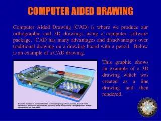
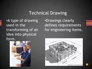
Computer Aided Technical Drawing 2012-2013. 1. The design process. Almost everything around us has been created by, or is influenced by, engineers: Buildings, vehicles, roads, railways, food growing and processing, books, medical care, recreation , etc.

E N D
1. The design process • Almost everything around us has been created by, or is influenced by, engineers: • Buildings, vehicles, roads, railways, food growing and processing, books, medical care, recreation, etc. • All of these have either been conceived and created from scratch or have evolved from existing ideas. Either way, an engineering design process will have been followed, in one form or another. • In essence, designs progress from : some statement of need to.. identification or specification of problem to.. search for solutions and finally to... development of solution to manufacture, test and use.
This sequence is usually iterative. It repeats until a satisfactory solution has evolved, as indicated in the flow diagram below.
1.2. The design model • The concept of the designer working with a model of a design is fundamental to the design process. • The design model is a representation of the design. This model could be anything from a few ideas in the designers head, through to rough sketches and notes, calculations, sets of detailed formal engineering drawings, computer generated 3D representations, physical prototypes, etc. • The design model would be used by the designer to record and develop ideas and to provide a basis to evaluate the design. • Larger design projects are undertaken by more than one engineer. Design models are used to communicate and demonstrate ideas between all those concerned with the product design, development, manufacture and use. • A designer needs to have the skills to generate and work with this model in order to communicate ideas and develop a design.
1.3. Types of design model • Designers use a variety of different models, depending on what property of the design is to be considered and for whom the information is destined. • Typically a designer may model: • Function • Structure • Form • Material properties, surface conditions • Within this module we will concern ourselves primarily with form, i.e. the shape of parts or components and how they fit together.
2. Projections • We have discussed both the role of the design model in the design process and the importance of the representation of the form or shape in this role. • Now we will consider in detail the methods designers use to represent the form of their designs. • Back in the 18th century a French mathematician and engineer, Gaspard Monge (1746-1818), was involved with the design of military armory. • He developed a system, using two planes of projection at right angles to each other, for graphical description of solid objects.
2.1. Orthographic projection • This system, which was, and still is, called Descriptive Geometry, provided a method of graphically describing objects accurately and unambiguously. It relied on the perpendicular projection of geometry from perpendicular planes. • Monge's Descriptive Geometry forms the basis of what is now called Orthographic Projection. • The word orthographic means to draw at right angles and is derived from the Greek words: • ORTHOS - straight, rectangular, upright • GRAPHOS - written, drawn Fig.1. Two right angle planes of projection
Orthographic projection is the graphical method used in modern engineering drawing. • There are two predominant orthographic projections used today. They are based on Monge'soriginal right angle planes. • They define four separate spaces, or quadrants. Each of these quadrants could contain the object to be represented. • Traditionally however, only two are commonly used, the first and the third. • Projections created with the object placed in the first quadrant are said to be in First Angleprojection, and likewise, projections created with the object placed in the third quadrant are said to be in Third Angle projection. First quadrant Fourth quadrant Third quadrant Second quadrant
2.2. First angle projection The OBJECT is FIRST for FIRST Angle projection. or... EYE > OBJECT > IMAGE or... You look through the object and place the image. • It is used in EU and it is composed by: • Observer • Object • Projection direction • Plane of projection
2.3. Third angle projection The PLANEis FIRST for THIRDAngle projection. or... EYE > IMAGE > OBJECT or... You look through the plane to the object. • It is used in USA and it is composed also by: • Observer • Object • Projection direction • Plane of projection, but the order is different
2.4. Orthographic projection symbols • Both systems of projection, First and Third angle, are approved internationally and have equal status. The system used must be clearly indicated on every drawing, using the appropriate symbol shown in the figure below: First Angle projection is more common in Europe Third Angle projection is widely used in both USA and UK Projection system symbols and recommended proportions
Examples: First Angle projection Third Angle projection
3. Projection systems • A projection is defined as an image of an object or an element from 3D space on a plane named projection plane. • The most usual projection systems are: • 1. The central projection; • 2. The parallel projection, with orthographic projection drawings as a particular case. Elements of the central projection system: [P] projection plane O - the center of the projection, O[P] A – a point in space, A[P]; O A The line OA[P] = a – the central projection Line OA represents the line for projection
Parallel projection system (left) is defined by the following: • [P] – The projection plan; • O – for this case O is situated at the infinity; • A – a point in space; A[P]; O A; • Lines for projection are parallel with a given direction; • The parallel line through A intersects plan [P] in a – parallel oblique projection; • If the direction is perpendicular on plane [P], the intersection point is a– parallel orthogonal projection (right).
3.1. Double orthogonal projection • Double orthogonal projection consists of: • Two perpendicular projection planes [V] – vertical – and [H] – horizontal • Their intersection line, OX, sometime named Earth line or ground line • The projection planes divide the space in 4 dihedron.
3.2. Triple orthogonal projection • For the case when the relative positions in space of the elements projected on the [H] and [V] does not allow to completely represent them, a supplementary projection plane is used, namely the lateral plane [L]. • The lateral plane [L] further divides the space into 8 trihedral. [H][V] = ox, [H][L] = oy, [V][L] = oz
3.3. Triple orthogonal projection in draught - epura Projections of A point on the 3 projection planes are: a – on horizontal plane [H] a’ – on vertical plane [V] a” – on lateral plane [L] [H][V] = ox, [H][L] = oy, [V][L] = oz By rotating planes [H] and [L] with 90 degr. around ox, respectively oy axe, one can obtain a planar representation of the three projection planes.
4. Pictorial Drawing • Orthographic projection is used as an unambiguous and accurate way of providing information, primarily for manufacturing and detail design. • This form of representation can however make it difficult to visualize objects. • Pictorial views can be created to give a more three dimensional impression of the object. • There are three types of pictorial projections commonly used, as shown below: Perspective projection Isometric projection Oblique pictorial projection
4.1. Perspective • Used more with freehand sketching and in architecture. • Parallel lines appear to converge and meet at what is referred to as the vanishing point. • You can have one, two or three vanishing points (VP):
4.2. Isometric projection • Receding lines drawn at 30º • Lines usually kept at true measured lengths.
4.3. Oblique projection • Front face sketched as a true shape. • Starts with two axes, one horizontal, one vertical. • The third axis is usually drawn at 45º and lengths are reduced by 50% of true lengths. • Sometimes called 'cabinet' projection.
5. Drawing conventions • In order for anyone to be able to understand exactly what a drawing represents, sets of precise rules and conventions have to be followed, much like a language. • These rules are usually referred to as Standards. • When a designer works with an engineering drawing they must be familiar with the precise meaning of the various line styles, abbreviations, drawing simplifications and terminology as specified in the relevant standards. • Standards are developed both privately by companies and by internationally recognized institutions. • Such international standards are: • ISO – International Standards Association • British Standard Institution: BS 8888 (SuperceededBS 308) • American National Standards Institute: Y14 series
5.2. Scales • The scale of an engineering drawing represents the ratio between the linear dimension measured on a drawing and the actual dimension of the real object of representation.
5.3. Lettering • All characters on a drawing must be legible and consistent, with consideration being given to the possibility of drawing reductions and poorer quality reproductions being made. • Characters should all be consistent on the same drawing. • Capital letters are preferred to lower case ones. • Size of lettering is given as a minimum height, relating to drawing size. • Example • Standardized lettering (IDT ISO 3098/1:1974), TypeB (d = h/10)
5.4. Paper formats • Formats(SR ISO 5457:1994) h – neutral zone, recommended: h = 10 mm for A2, A3 and A4 h = 20 mm for A0 and A1
5.5. Indicator and table of components • Any technical drawing must be provided with an indicator. • The indicator is situated always at the lower –right corner of a drawing. • It consists of a compact group on rectangles, which must provide information regarding both: • - Identification information • - Supplementary information
Information provided by the identification zone: • The registry number of the drawing • The name of the drawing • The name of the legal owner of the drawing • The supplementary information zone provides information related to: • A symbol that indicates the design method • The main scale of the drawing • The unity of measure for linear dimensions • The method to indicate the state of the surface • The method to indicate the geometrical tolerances • The format of the paper of the drawing • The data of the first edition of the drawing
The table of components could be placed above the indicator, or on a separate document; in this last case it must carry the same number as the original drawing. • The table is drawn with thick lines, and provides information regarding: • Position – the position number of the component; • Naming – the name of the component; • Quantity – the total number of identical components; • Reference – the number of the execution drawing, the standard, a code or any other similar information; • Material – the type and quality of the materials; if it is a standardized material the standardized notation must be used.
5.6. Projections layout The engineering drawing of an object is intended to provide information regarding two main topics: • To establish the geometrical forms of the specific object; • To define the dimensions a relative positions of the above geometrical forms. According to the complexity of the object, it could be represented by means of 1, 2, 3, 4, 5 or 6 projections, and could include sections, too.
View from below Right view Left View Back view Front view Top view
6. Creating orthographic projection drawing The component: Your drawing will, for this example consist of four views: • Front F • Left L • Right R • Plan (Top) P Usual practice is to orient the component in a position that it is most likely to be found in. Your aim is to create, from the front view, an orthographic projection drawing as shown in figure. Note how the views are constructed in line with each other, allowing the features to be 'projected' between the views.
The stagesof the drawing process are: 1) Choose which view direction or face will be used as the front view of the component. 2) Draw the outline of the front view, leaving room for the other views. 3) Draw feint construction lines out from the front view. 4) Start to draw the outlines of the other views, using sides you know the length of. 5) Complete the details of the views by adding any required hidden detail lines, other outlines and center lines.