Download
1 / 46
630 likes | 1.2k Views
Technical Drawing. Designing things on paper. Conceptual Sketches. When you first get an idea for something you want to build you may draw it roughly, without using instruments or accurate scales. This is called a conceptual sketch. Types of Drawings. All Drawings. Technical. Artistic.

E N D
Technical Drawing Designing things on paper
Conceptual Sketches • When you first get an idea for something you want to build you may draw it roughly, without using instruments or accurate scales. This is called a conceptual sketch.
Types of Drawings All Drawings Technical Artistic Drawings (technical/engineering) Diagrams (design & technical) Sketches (conceptual) simulated perspective Diagram (design plan) Diagram (technical) Oblique projection Isometric projection Multi view orthographic Less technical More technical
A conceptual sketch… • Allows an idea to be expressed quickly in graphic form • Is prepared free-hand (without drawing instruments) • Is not done to scale, but it respects the rules of technical drawing as much as possible, and is made roughly proportional to the object represented.
Technical Drawings • Serve as a reference to workers, architects or machinists. • When you are ready to design the details, you make a technical drawing, done with more detail and more accuracy.
Difference: • Sketch: made without drafting tools... Just pencil and paper. Scale is approximate, not accurate, but the sketch should still look like the object. • Drawing: made with drafting tools... Ruler, set squares, protractor and compass. Scale should be accurate and the drawing carefully made.
A technical drawing… • Presents all the information necessary for the object’s construction. • Is made with great precision, • Requires the use of rulers, compass and protractor or drafting software. • Is done to scale, and respects the proportions of the object represented. • Respects conventions in the mode of the representation.
Basic Lines (part 1) 8 cm
Technical Drawing of Fighter Plane(Isometric Projection, exploded view)
Technical drawings can represent things… as simple as a spoon, or… Technical Drawing of a spoon Multi-view, Orthographic projection
as complex as a space ship Photograph of Mercury Spacecraft Technical Drawing of Mercury Spacecraft, Top View, Orthographic Technical Drawing of Mercury Spacecraft, Isometric Projection
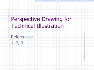
Projections • Perspective projections • Multi-view projections • Isometric projection • Oblique projection
Vanishing Point True Perspective • Objects drawn in true perspective look realistic. • They have “vanishing points” where straight lines seem to converge • They can have one, two or three vanishing points, depending on how much the artist wants to work. • But in true perspective, objects far away will be drawn smaller than nearby objects… not a good idea in technical drawing! Vanishing Points Vanishing Points
Now that you have seen how nice perspective drawings can be... • FORGET ABOUT THEM! • We hardly ever use perspective projections when doing technical drawing. • They are too much work, and they don’t show all the details we may need to show. • Also, they distort both angles and dimensions. • Leave them for ART class...
Isometric Projection(a simulated perspective drawing style) • Isometric (or simulated perspective) drawings look at first like perspective drawings… • But the lines don’t converge. There are no vanishing points and distant objects are the same size as nearby ones. • Right angles in isometric projections are usually represented by 60° or 120° angles. 60˚ Represents 90˚ Represents 90°
More isometric drawings Warning: Your workbook classifies isometric drawings as “perspective” drawings, but they are not true perspective. They resemble perspective drawings but in a true perspective drawing, distant objects are drawn smaller. In isometric drawing, distant objects are not smaller..
Oblique Projectionanother “simulated” perspective • Similar to isometric projection, it is also a “simulated perspective” • In oblique projections, the side of the object facing you is drawn “square” and accurate (that is with right angles at 90° and its measurements proportional) • The sides not facing you are distorted • Warning: Your workbook calls this oblique perspective, but it is not a true perspective. This side is not! This side is accurate 90° 90° =60°
Orthographic Projections • Orthographic projections “flatten” one view of the object onto a sheet of paper, while retaining the correct proportions (angles and dimensions) • Maps are an example of orthographic projection (a top view) • The trouble with orthographic projections is that one view usually isn’t enough. • Maps and floor-plans are exceptions, where one top-view is often enough.
Orthographic Projection(Multi-view) • Draws an object as it would be seen from several different directions • The views are “flat”, with all angles shown correctly and all measurements to scale.
Comparing Projections • Perspective drawings look nicer when used by an artist, but… • Isometric, oblique and multi-view drawings give more accurate information when used in technical drawing. • Isometric drawings show accurate dimensions, but distorted angles. • Oblique drawings give accurate dimensions for one side only. • Orthographic (multi-view) are the best choice for most technical drawing. Oblique Orthographic (multi-view)
Scale • SCALE is the relationship between the measurement of an object drawn on a sheet of paper, and the measurements of the actual object. • Often technical drawings are made a different size from the objects they represent. • Scale-reduction is when the drawing is smaller than the actual object • Scale-increase is when the drawing is larger than the actual object.
Dimensioning • When a drawing is done to scale, you should label it with its dimensions. • Use dimension lines to label each dimension, with extensions where necessary • You should label just enough edges to show all the dimensions, but you don’t need to repeat. • In Canada (at least for science) dimensions are usually given in millimetres (mm). If you use different units (cm, in, feet etc.) you need to write the unit. You do not need to write mm if all of your dimensions are in millimetres. • Angles can be shown in degrees (°), diameter by Ø, and radius by R
300 means 300mm unless another unit is specified Dimensioning A Toy Truck How to label an angle. Ø means diameter (R would be radius) How to label small dimensions.
Dimensioning Dimensions can also be shown on isometric drawings, but you have to be a bit more careful. Also, you should only show the most important dimensions on an isometric drawing.
Diagrams • Diagrams are simplified versions of a drawing. Diagrams show how an object works, not necessarily how it looks. • Diagrams often use abstract symbols rather than actual pictures to represent things.
A Circuit Diagram • Doesn’t show what the circuit looks like, but tells an electrician how its all connected.
Diagram of Energy Conversion Unit • It doesn’t show what the unit looks like, but rather, what it does or how it works.
Exploded Views • A diagram that shows an object “taken apart” is sometimes called an exploded view.
Chapter 11 Questions • 1. Two common drawings used in technology are: Engineering (or technical) Drawings and Diagrams. • 2. Technology is a set of techniques used by humans to design, build, and maintain objects and systems that we need or want. • 3. (c) Cutting Plane lines and Construction Lines are not shown.
4. Geometric Lines • A) the main drafting instruments are: T-square, set-squares, ruler, pencil and compass • B) The three types of straight line are: horizontal, vertical, and oblique. • C) Two drafting instruments that can draw circles are the compass and the circle template. • 5. The Stop Signs: The stop sign on the left is a sketch, since it appears to be drawn freehand. The one on the right was drawn using tools. • 6. Projections: • A) The rays are perpendicular in multi-view and isometric projections • B) these are called orthogonal projections
7. The six views are: • Top view, Front view, Right Side view • Bottom view, Back (or Rear) view, Left Side view • 8. The three drawings: • #1 oblique projection, #2 isometric, #3 multi-view (or orthographic view) • #1 and #2 are the “perspective” drawings. (actually they are “simulated perspective” drawings rather than true artistic perspective) • 9. Views • A matches 3, B matches 1 • C matches 4, D matches 2
10. Jonathan is building a model car. He is reducing the measurements 40 times. • The scale he is using is a scale reduction. • It is indicated by 1:40 • The finished model will be 100 mm long (or 10 cm) • 11. The diagram of the soccer field has a scale of 1:2000, so... (hint: use your ruler) • The width of the actual field is 68000 mm (or 68m) • The length of the actual field is 104000 mm (104m) • 12. The dimensions of the skateboard are: • Length = 790 mm (or 79 cm) • Width = 210 mm (or 21 cm) • Diameter of wheels = 60 mm
13. The maximum difference between the measurement on the diagram, and the real-life measurement is called the tolerance. • 14. Match the objects to their cross sections: • A matches 1 • B probably matches 3, (but could match 2) • C probably matches 2, (but could match 3) • 15. Look at the diagram of the wrench. • Section [B]is octagonal • Section [C] is circular (or round) • The sections are aligned, they are shown inside the drawing of the wrench instead of outside of it.
16. Diagram of kitchen scale • A) The force is exerted on the tray • B) 7 regular screws were used, plus one bolt (which is a type of screw) so I would also accept an answer of 8. • C) The rod can move up and down ( or, more accurately, has bidirectional translation) • D) The coil spring allows the rod to return to its initial position.
Define: • Technology Technical Drawing • Basic Lines Geometric Lines • Sketch Projection • Isometric (projection) Oblique (projection) • Orthagonal (proj.) Multiview (projection) • General drawing Exploded drawing • Detail drawing Scale • Dimensioning Tolerance • Section Cross section • Diagrams: design, technical, and circuit
Basic Lines to Know • Visible(or object) • Hidden • Construction • Centre • Dimension and extension • Cutting Plane • Hatching • Leader (or reference)
Geometric Lines to know • Horizontal (straight) • Vertical (straight) • Oblique • Ellipse (and circle) • Curve
Methods of Drawing • Sketching • Drafting • Computer Assisted Design (C.A.D.)
Projections • Multiview (orthagonal) • Isometric • Oblique
Scale • Dimensioning • Calculating Scale
Diagrams • Design plan diagrams • Technical diagrams • Circuit diagrams • Symbols for • Forces or constraints • Movement • Parts (screw or bolt, nut, guides) • Electrical circuits