Download
1 / 7
70 likes | 72 Views
This article discusses the practical reasons why G0 needed position feedback while HAPPEX did not. It analyzes the differences in position values between the two experiments and explores possible factors such as analyzing power, alignment procedures, and settings choices. The article also examines adiabatic damping results and helicity-correlated beam properties during HAPPEX.

E N D
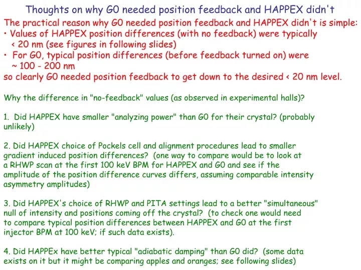
Thoughts on why G0 needed position feedback and HAPPEX didn't • The practical reason why G0 needed position feedback and HAPPEX didn't is simple: • Values of HAPPEX position differences (with no feedback) were typically • < 20 nm (see figures in following slides) • For G0, typical position differences (before feedback turned on) were • ~ 100 - 200 nm • so clearly G0 needed position feedback to get down to the desired < 20 nm level. • Why the difference in "no-feedback" values (as observed in experimental halls)? • 1. Did HAPPEX have smaller "analyzing power" than G0 for their crystal? (probably • unlikely) • 2. Did HAPPEX choice of Pockels cell and alignment procedures lead to smaller • gradient induced position differences? (one way to compare would be to look at • a RHWP scan at the first 100 keV BPM for HAPPEX and G0 and see if the • amplitude of the position difference curves differs, assuming comparable intensity • asymmetry amplitudes) • 3. Did HAPPEX's choice of RHWP and PITA settings lead to a better "simultaneous" • null of intensity and positions coming off the crystal? (to check one would need • to compare typical position differences between HAPPEX and G0 at the first • injector BPM at 100 keV; if such data exists). • 4. Did HAPPEx have better typical "adiabatic damping" than G0 did? (some data • exists on it but it might be comparing apples and oranges; see following slides)
Helicity-Correlated Beam Properties: Experience during HAPPEx Helium
Helicity-Correlated Beam Properties: Experience during HAPPEx Hydrogen
HAPPEX adiabatic damping results from Ryan Snider 1=BPM0I05 2=BPM0L01 3=BPM0L02 4=BPM0L03 5= BPM0L04 BPM4A and BPM4B are in Hall A
HAPPEX adiabatic damping results from Ryan Snider 1=BPM0I05 2=BPM0L01 3=BPM0L02 4=BPM0L03 5= BPM0L04 BPM4A and BPM4B are in Hall A
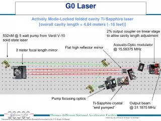
G0 results on "adiabatic damping" from PZT scans 100 keV 5 MeV 3 GeV Total observed damping from 100 keV to 3 GeV: x ~ 24, y~ 10 Most of damping comes from 5 MeV 3 GeV region
Recall: Beam Specs./Observed values for G0 Forward Angle Run Beam specifications table for G0 forward angle run: Observed values during G0 forward angle run: