Download
1 / 34
340 likes | 529 Views
Cell Broadband Processor. Daniel Bagley Meng Tan. Agenda. General Intro History of development Technical overview of architecture Detailed technical discussion of components Design choices Other processors like the cell Programming for the cell. History of Development.

E N D
Cell Broadband Processor Daniel Bagley Meng Tan
Agenda • General Intro • History of development • Technical overview of architecture • Detailed technical discussion of components • Design choices • Other processors like the cell • Programming for the cell
History of Development • Sony Playstation2 • Announce March 1999 • Released March 2000 in Japan • 128bit “Emotion Engine” • 294mhz, MIPS CPU • Single Precision FP Optimizations • 6.2gflops
History Continued • Partnership between Sony, Toshiba, IBM • Summer of 2000 – High level development talks • Initial goal of 1000x PS2 Power • March 2001, Sony-IBM-Toshiba design center opened • $400m investment.
Overall Goals for Cell • High performance in multimedia apps • Real time performance • Power consumption • Cost • Available by 2005 • Avoid memory latency issues associated with control structures
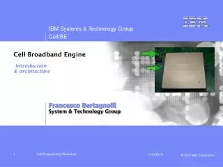
The Cell itself • Power PC based main core (PPE) • Multiple SPEs • On die memory controller • Inter-core transport bus • High speed IO
Cell Implementation • Cell is an architecture • Preliminary PS3 Implementation • 1 PPE • 7 SPE (1 Disabled for yield increase) • 221 mm² die size on a 90 nm process • Clocked at 3-4ghz • 256GFLOPS Single Precision @ 4ghz
Why a Cell Architecture • Follows a trend in computing architecture • Natural extension of dual and multi-core • Extremely low hardware overhead • Software controllable • Specialized hardware more useful for multimedia
Possible Uses • Playstation3 (Obviously) • Blade servers (IBM) • Amazing single precision FP performance • Scientific applications • Toshiba HDTV products
Power Processing Element • PowerPC instruction set with AltiVec • Used for general purpose computing and controlling SPE’s • Simultaneous Multithreading • Separate 32 KB L1 Caches and unified 512 KB L2 Cache
PPE (cont.) • Slow but power efficient PowerPC instruction set implementation • Two issue in-order instruction fetch • Conspicuous lack of instruction window • Compare to conventional PowerPC implementations (G5) • Performance depends on SPE utilization
Synergistic Processing Element (SPE) • Specialized hardware • Meant to be used in parallel • (7 on PS3 implementation) • On chip memory (256kb) • No branch prediction • In-order execution • Dual issue
SPE Architecture • 0.99µm2 on 90nm Process • 128 registers (128 bits wide) • Instructions assumed to be 4x 32bit • Variant of VMX instruction set • Modified for 128 registers • On chip memory is NOT a cache
SPE Execution • Dual issue, in-order • Seven execution units • Vector logic • 8 single precision operations per cycle • Significant performance hit for double precision
SPE Local Storage Area • NOT a cache • 256kb, 4 x 64kb ECC single port SRAM • Completely private to each SPE • Directly addressable by software • Can be used as a cache, but only with software controls • No tag bits, or any extra hardware
SPE LS Scheduling • Software controlled DMA • DMA to and from main memory • Scheduling a HUGE problem • Done primarily in software • IBM predicts 80-90% usage ideally • Request queue handles 16 simultaneous requests • Up to 16 kb transfer each • Priority: DMA, L/S, Fetch • Fetch / execute parallelism
SPE Control Logic • Very little in comparison • Represents shift in focus • Complete lack of branch prediction • Software branch prediction • Loop unrolling • 18 cycle penalty • Software controlled DMA
SPE Pipeline • Little ILP, and thus little control logic • Dual issue • Simple commit unit (no reorder buffer or other complexities) • Same execution unit for FP/int
SPE Summary • Essentially small vector computer • Based on Altivec/VMX ISA • Extensions for DMA and LS management • Extended for 128x 128bit registerfile • Uniquely suited for real time applications • Extremely fast for certain FP operations • Offload a large amount on to compiler / software.
Element Interconnect Bus • 4 concentric rings connecting all Cell elements • 128-bit wide interconnects
EIB (cont.) • Designed to minimize coupling noise • Rings of data traveling in alternating directions • Buffers and repeaters at each SPE boundary • Architecture can be scaled up with increased bus latency
EIB (cont.) • Total bandwidth at ~200GB/s • EIB controller located physically in center of chip between SPE’s • Controller reserves channels for each individual data transfer request • Implementation allows for SPE extension horizontally
Memory Interface • Rambus XDR memory to keep Cell at full utilization • 3.2 Gbps data bandwidth per device connected to XDR interface • Cell uses dual channel XDR with four devices and 16-bit wide buses to achieve 25.2 GB/s total memory bandwidth
Input / Output Bus • Rambus FlexIO Bus • IO interface consists of 12 unidirectional byte lanes • Each lane supports 6.4 GB/s bandwidth • 7 outbound lanes and 5 inbound lanes
Design Choices • In-order execution • Abandoning ILP • ILP – 10-20% increase per generation • Reducing control logic • Real time responsiveness • Cache Design • Software configuration on SPE • Standard L2 cache on PPE
Cell Programming Issues • No Cell compiler in existence to manage utilization of SPE’s at compile time • SPE’s do not natively support context switching. Must be OS managed. • SPE’s are vector processors. Not efficient for general-purpose computation. • PPE’s and SPE’s use different instruction sets.
Cell Programming (cont.) • Functional Offload Model • Simplest model for Cell programming • Optimize existing libraries for SPE computation • Requires no rebuild of main application logic which runs on PPE
Cell Programming (cont.) • Device Extension Model • Take advantage of SPE DMA • Use SPE’s as interfaces to external devices
Cell Programming (cont.) • Computational Acceleration Model • Traditional super-computing methods using Cell • Shared memory or message passing paradigm for accelerating inherently parallel math operations • Can overwrite intensive math libraries without rewriting applications
Cell Programming (cont.) • Streaming model • Use Cell processor as one large programmable pipeline • Partition algorithms into logically sensible steps. Execute each separately, in serial, on separate processors.
Cell Programming (cont.) • Asymmetric Thread Runtime Model • Abstract Cell architecture away from programmer. • Use OS to use processors to each run different threads.
Sample Performance • Demonstration physics engine for real-time game • http://www.research.ibm.com/cell/whitepapers/cell_online_game.pdf • 182 Compute to DMA ratio on SPE’s • For the right tasks, Cell architecture can be extremely efficient.