Download
1 / 1
10 likes | 134 Views
Echidna – the Engineering Challenges. Echidna positioner. Main structural plate. Focal Plane Imager (FPI). Pivoting ball of a science spine. 3 Hemispheres (one not visible). Triangular magnet. 12.35 mm. Electrodes. 420 mm. 42 Piezo actuators. PCB electronic board. Piezo tube.

E N D
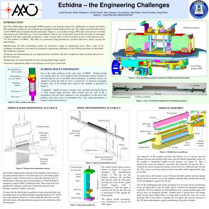
Echidna – the Engineering Challenges Echidna positioner Main structural plate Focal Plane Imager (FPI) Pivoting ball of a science spine 3 Hemispheres (one not visible) Triangular magnet 12.35 mm Electrodes 420 mm 42 Piezo actuators PCB electronic board Piezo tube Pivoting ball Top bar 26.850±0.015 Ball keeper plate Echidna module Magnet keeper plate Mounting surface of the module Spring “Blade type” module mounting bracket Module mounting surface Piezo actuator 160±0.015 - 50 µm Module PCB C - bracket +50 µm Radius 10 µm Spine tip positioned on the focal plane 15.50 ± 0.02 Mounting frame for modules Counterweight Pivoting ball 3-point mount Spine 160 ±0.015 Spine tip Shim Bottom plate Jurek Brzeski, Peter Gillingham, David Correll, John Dawson, Anna Moore, Rolf Muller, Scott Smedley, Greg Smith ANGLO – AUSTRALIAN OBSERVATORY INTRODUCTION The Fiber Multi-Object Spectrograph (FMOS) project is an Australia-Japan-UK collaboration to design and build a fiber positioner feeding two near infrared spectrographs from the Subaru telescope. The Anglo-Australian Observatory (AAO) FMOS project includes the fiber positioner (Figure 1), a focal plane imager (FPI) and a corrector lens. Echidna will position up to 400 fibers in a 30 arc min diameter field of view at the prime focus of the telescope. Its advantage, compared with other multi-fiber positioners, is that so many fibers can be positioned in such a small physical area – 147 mm diameter in FMOS. The fibers are positioned using piezoelectric actuators that move spines carrying the optical fibers. • Manufacturing the fiber positioning system has presented a range of engineering issues. Here, some of the techniques developed to overcome key mechanical engineering challenges for the Echidna positioner are described. The challenges included: • designing and manufacturing of very high precision assemblies and their components with assembly tolerances in the 10s of microns; • finding space for many hundreds of wires carrying high voltage signals; • selection of appropriate adhesives for joining several types of materials; ECHIDNA SPACE CONSTRAINTS One of the major problems in the early stage of FMOS – Echidna design was finding space for a few hundred micro positioning actuators (Figure 2) and allowing for ease of assembly and maintenance. A modular system was adopted in which the field of view is covered by 12 identical rectangular modules. One of the module bases (part of the module) is presented in Figure 3. “Triangular” magnet for piezo actuators were specially developed (Figure 2). This magnet shape provides 100% contact area for each of the 3 hemispheres and the force imparted to the hemispheres by the pivot ball produces only shear stress in hemisphere base. This makes hemisphere to magnet connection permanent. Figure 1. View of Echidna positioner mounted on FMOS main structural plate Figure 3. One of 12 identical module bases of Echidna positioner Figure 2. Piezo actuator and spine MODULE BASE POSITIONING ACCURACY SPINE TIP POSITIONING ACCURACY MODULE ASSEMBLY Figure 6. Module base assembly jig The objective of the module assembly jig (Figure 6) is to ensure that the distance between the pivoting ball center and the bottom (mounting) surface of the module is maintained within several microns (see Figure 5). This is achieved by using two identical c-brackets and extremely flat top bar. The c-brackets are used to mount the module on the lower face while the top is for the bar. This creates a reference plane for the 6 mm balls which represent the spine pivot balls. To ensure that a full contact occurs between the balls and the top bar, springs placed inside the piezos, act on the magnets, pushing them and the ball resting on the hemispheres, against the top bar. One of the challenging tasks in the jig design was to ensure precise positioning of the pivoting balls in the XY plane and to constrain the triangular magnets angularly. The best solution for both problems was a magnet keeper plate with precise laser cut triangular profiles. Another plate is placed above the keeper plate has precisely drilled holes to accept balls (exactly the same size as the pivoting balls of the spines). Together the two plates give precise location in the XY plane and adequate angular positioning of the piezo actuator. Figure 5. Spine tip positioning accuracy For control of the spine accuracy (shown in Figure 5), a jig was designed and manufactured (Figure 7). This jig sets the distance between the pivoting ball and the spine tip. The spine pivoting ball seats on the 3-point mount (magnet with 3 hemispheres). After the spine is inserted into the jig, the fiber tip is positioned to butt against the bottom plate The spines’ length consistency was confirmed to ± 10 µm for 90% spines. Figure 4. Module base positioning accuracy The module support plate carrying all the modules must retain an accurate position relative to the telescope axis at all zenith angles. The plate is made of Stavax steel to match the material of the 12 module bases while the main structural plate on which Echidna is mounted is made of MIC-6 aluminum alloy. These materials have significantly different coefficients of thermal expansion and therefore cannot be rigidly connected. To cope with the differential expansion of main structural plate and mounting frame for modules flexible mounting brackets of a “blade” type were designed (Figure 4). In the radial direction they can flex with little stress, allowing thermal expansion and contraction of the two materials. Figure 7. Spine jig assembly jig