Download
1 / 58
590 likes | 617 Views
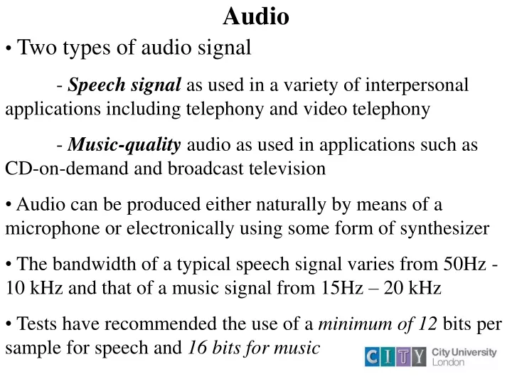
Two types of audio signal - Speech signal as used in a variety of interpersonal applications including telephony and video telephony - Music-quality audio as used in applications such as CD-on-demand and broadcast television

E N D
Two types of audio signal • - Speech signal as used in a variety of interpersonal applications including telephony and video telephony • - Music-quality audio as used in applications such as CD-on-demand and broadcast television • Audio can be produced either naturally by means of a microphone or electronically using some form of synthesizer • The bandwidth of a typical speech signal varies from 50Hz - 10 kHz and that of a music signal from 15Hz – 20 kHz • Tests have recommended the use of a minimum of 12 bits per sample for speech and 16 bits for music Audio
Initially a PSTN operated with analogue signals throughout, the source speech signal being transmitted and switched • However, today these have been replaced with digital circuits • In order to support interworking of the analogue and digital circuits the design of the digital equipment is based on the analogue network operating parameters • The BW of a speech circuit was limited to 200 Hz to 3.4 kHz • The digitization procedure is known as pulse code modulation • PCM (pulse code modulation) is a digital scheme for transmitting analogue data. PCM – Pulse Code Modulation
PCM Speech – Compressor/Expander Characteristics • In linear quantization irrespective of the signal amplitude same level of quantization noise is produced ( noise level is same for the quiet signals and loud signals) • Pulse Code Modulation consists of two additional circuits: Compressor (encoder) and Expander (decoder) to help reduce the effect of quantization noise with just 8 bits per sample, making the intervals non-linear with narrower intervals for small amplitude signals than larger amplitude signals. This is achieved by the means of the compressor circuit • The analogue output from the DAC is passed to the expander circuit which performs the reverse operation of the compressor circuit • The overall operation is known as companding • The compression and expansion characteristics is known as A-law in Europe
Synthesized audio • The computer takes input commands from the keyboard and outputs these to the sound generators which produce the corresponding sound waveform to drive the speakers
Synthesized audio is often used since the amount of memory required can be between two or three orders of magnitude less than that required to store the equivalent digitised waveform version • The three main components of an audio synthesizer are the computer (with various application program), the keyboard (based on that of a piano) and the set of sound generators • The computer takes the commands and outputs these to the sound generators which in turn produce the corresponding sound waveform – via DACs to drive the speakers Synthesized Audio
Pressing a key has similar effects to pressing a keyboard of a computer. For each key press a different codeword (message – indicating the key pressed and the pressure applied) is generated • The control panel contains range of different switches and sliders that collectively allow the user to indicate to the program information such as the volume of the generated output and selected sound effects to be associated with each key • To discriminate between the inputs from different possible sources a standard known set of messages (also includes the type of connectors, cables, electrical signals, etc) have been defined: Music Instrument Digital Interface (MIDI) Synthesized Audio
Status byte - This defines the particular event that has caused the message to be generated • Data bytes – Which collectively define a set of parameters (pressure applied, identity of the key) associated with the event • Event – A key being pressed • It is important to identify the different types of instruments that generated the events • Each instrument has a MIDI code associated with it – e.g Piano has a code of 0 and violin 40 • Since the music is in the form of MIDI messages it is vital to have a sound card in the client computer to interpret the sequence MIDI
The three main properties of a colour source that the eye makes use of are: • - Brightness: represents the amount of energy that stimulates the eye (from black-lowest to white-highest) • - Hue: Represents the actual colour of the source (each colour has a different frequency/wavelength) • - Saturation: represents the strength of the colour • Luminance is used to refer to the brightness of a source, and hue and saturation (concerned with its colour) are referred to as chrominance characteristics • The combination of the three signals Y ( amplitude of luminance signal), Cb (blue chrominance) , and Cr (red chrominance) contains all the necessary information to describe a colour signal Colour Signals
Principles of colour TV transmission • Colour transmission is based on two facts - The first is that all colours may be produced by the addition of appropriate quantities of the three primary colours: RGB E.g: Yellow = R + G Magenta = R + B White = R + G + B • Yellow and magenta are known as complementary colours - The second fact is that human eye reacts predominantly to the luminance (black and white) components of a colour picture, much more than to its chrominance (colour) component
Principles of colour TV transmission • Colour TV transmission involves the simultaneous transmission of the luminance and chrominance components of a colour picture, with luminance predominant over chrominance • As for the chrominance component, it is first ‘purified’ by removing the luminance component from each primary colour, resulting in what is known as colour difference signals: R-Y G-Y B- Y
Principles of colour TV transmission • Since the luminance signal Y= R + G + B, only two colour difference signals need to be transmitted, namely R-Y and B-Y • The third colour difference, G-Y may be recovered at the receiver from the three transmitted components: Y, R-Y and B-Y • In analogue TV broadcasting, the two colour difference signals R-Y and B-Y are known as U and V respectively • In digital television they are referred to as Cr and Cb
Signal Bandwidth Baseband spectrum of colour TV in NTSC System • I signal bandwidth – 2 MHz • Q signal – bandwidth – 1 MHz • In NTSC the eye is more responsive to the I signal than the Q signal, hence maximizing the available bandwidth and minimizing the level of interference with the luminance signal is needed
Signal Bandwidth - Baseband spectrum of colour TV in PAL System • In PAL, the larger luminance bandwidth allows both the U and V chrominance signals to have the same modulated bandwidth • U and V chrominance signals have the same modulated bandwidth of 3 MHz. • The addition of the sound and video signal is called the complex baseband signal
Analogue Colour Encoding • There are three main systems of analogue colour encoding: NTSC (used in USA), PAL (used in UK) and SECAM (used in France) • All three systems split the colour picture into luminance and chrominance • All three types use the colour difference signals to transmit the chrominance • SECAM transmits the colour difference signals on alternate lines • The other two systems NTSC and PAL transmit both chrominance components simultaneously using a technique known as Quadrature amplitude modulation (QAM)
Digital Video • With digital television it is more usual to digitize the three component signals separately prior to their transmission to enable editing and other operations to be readily performed • Since the eye is less sensitive for colour than it is for luminance, a significant saving in terms of resulting bit rate can be achieved by using the luminance and two colour difference signals instead of the RGB directly • Digitization formats exploit the fact that the two chrominance signals can tolerate a reduced resolution relative to that used for the luminance signal
4:2:2 Sampling Structure • There are several structures for subsampling the chrominance components • One way is to sample the chrominance components every other pixel known as the 4:2:2 sampling structure • This reduces the chrominance resolution in the horizontal dimension only leaving the vertical resolution unaffected • The ratio 4:2:2 (Y: CR: CB) indicates that both CR and CB are sampled at half the rate of the luminance signal
4:2:2 Format (4Y, 2Cb, 2Cr) • Used in television studios • Bandwidth up to 6MHz for the luminance signal and less than half this for the chrominance signals
4:2:0 Format • It is a derivative of the 4:2:2 format and is used in digital video broadcast applications (achieving good picture quality)
Digital Processing • Logic Gates • A logic gate is a device whose output depends on the combination of its inputs • For instance, an AND gate produces a logic 1 (high) output if and only if all its inputs are high
A digital package of information consists of a number of bits grouped together to form a word which is the basic unit of information • e.g an 8-bit word or a 16-bit word • A word can only make sense when all the bits have been received • In serial transmission the bits are sent one at a time along a single line • In parallel transmission the bits are transmitted simultaneously Serial and Parallel communication
Shift Registers • A shift register is a temporary store of data, which may then be sent out in a serial or parallel form • SISO shift register • When the register is full, the stored data in the register may then be clocked out serially, bit by bit • This type of register is called a serial-in-serial-out (SISO) shift register • The other types of registers are serial-in-parallel-out (SIPO) and parallel-in-serial-out (PISO) b0 b1 b2 b3 b7 Serial data in Serial data out
Multiplexing • Communication invariably involves transmitting several programmes via the same communication media, such as cable, satellite or terrestrial links • This may be achieved in two ways: • - Broadband using frequency division multiplexing (FDM) • - Baseband using the time division multiplexing (TDM) • FDM involve dividing the available bandwidth into several channels; each channel is then allocated to a single programme • The programmes are thus transmitted simultaneously
Multiplexing • In TDM the programmes are transmitted sequentially • Each programme is allocated a time slot during which the whole of the bandwidth of the medium is made available to it • At the receiving end the transmitted data is demultiplexed to obtain the required programme
Multiplexing • TDM is most efficient if all programmes carry the same amount of data • If they do not, i.e. if the traffic is uneven, some time slot will be underutilized while other time slots may not be able to handle the data stream • To avoid this a technique called statistical TDM is used
Statistical multiplexing • In this technique the allocation of time slots is based on the amount of traffic each programme generates • Time slots are allocated according to need • Programmes that generate heavy traffic are allocated more time slots while those with lighter traffic are allocated fewer time slots
Error control techniques • In all types of communication system, errors may be minimized but they cannot be avoided completely, hence the need for error correction techniques • If an error is detected at the receiving end, it can be corrected in two different ways: • - the recipient can request the original transmitter for a repeat of the transmission • - or the recipient can attempt to correct the errors without any further information form the transmitter • Whenever possible the communication systems tend to go for retransmission • However if the distances are large, perhaps to contact a space probe, or if real time signals are involved then retransmission is not an option. These cases require error correction techniques
The most basic technique, parity, provides the fundamental error correction • It involves a single parity bit at the end of a digital word to indicate whether the number of 1’s is even or odd • Even parity is when the complete coded data including the parity bit contains an even number of 1’s • odd parity is when the complete coded data contains an odd number of 1’s • At the receiver end the number of 1s is counted and checked against the parity bit. A difference indicates an error Parity bit 1 1 1 0 1 1 0 1 1 0 0 1 0 0 0 0 Even parity 1 1 1 0 1 1 0 0 Odd parity 1 0 0 1 0 0 0 1
Forward error correction • The simple parity check can only detect an error occurring in a single bit • An error affecting two bits will go undetected. Hence more sophisticated techniques are needed and one such method is the forward error correction (FEC) employed in digital television broadcasting • The introduction of the redundancy bits to a package of data increases the data length and with it the number of possible combinations • Consider a 6-bit package consisting of 4 bits of useful data and 2 redundancy • The 4 bits of useful data contain 24 = 16 different valid messages
Forward error correction • At the receiving end, however a set of 26=64 different messages may be received, of which only a subset contains the valid 16 messages • This subset is called a code • The valid messages are called code words or code vectors (vectors for short) • When a message is received that does not correspond to any of the valid code words, the receiver finds a valid code word ‘nearest’ to the received message, on the assumption that the nearest is the most likely correct message • e.g: consider a 1-bit word has two valid messages 0 and 1 which are now represented by 3-bits say 010 and 101. These are the only valid codewords out of the 23=8. Means if any of the other code words are received- 000, 001, 011, 100, 111 -then an error has occurred
Forward error correction • The invalid codewords can be divided into those which are nearest to 010 i.e those that differ from 010 by one digit only and those nearest to 101, i.e those that differ from 101 by one digit • Nearest to 010nearest to 101 • 011 001 • 110 100 • 000 111 • Suppose the invalid code word 011 is received; it can be corrected because it is most likely intended to be 010. It could have been 011 with two bits corrupted but the probability of that happening is less likely
Image Compression – JPEG encoder schematic • The Joint Photographic Experts Group forms the basis of most video compression algorithms
Image Compression – Image/block preparation • Source image is made up of one or more 2-D matrices of values • 2-D matrix is required to store the required set of 8-bit grey-level values that represent the image • For the colour image if a CLUT is used then a single matrix of values is required • If the image is represented in R, G, B format then three matrices are required • If the Y, Cr, Cb format is used then the matrix size for the chrominance components is smaller than the Y matrix ( Reduced representation)
Image Compression – Image/block preparation • Once the image format is selected then the values in each matrix are compressed separately using the DCT • In order to make the transformation more efficient a second step known as block preparation is carried out before DCT • In block preparation each global matrix is divided into a set of smaller 8X8 submatrices (block) which are fed sequentially to the DCT
Image Compression – Image Preparation • Once the source image format has been selected and prepared (four alternative forms of representation), the set values in each matrix are compressed separately using the DCT)
Image Compression – Forward DCT • Each pixel value is quantized using 8 bits which produces a value in the range 0 to 255 for the R, G, B or Y and a value in the range –128 to 127 for the two chrominance values Cb and Cr • If the input matrix is P[x,y] and the transformed matrix is F[i,j] then the DCT for the 8X8 block is computed using the expression:
Image Compression – Forward DCT • All 64 values in the input matrix P[x,y] contribute to each entry in the transformed matrix F[i,j] • For i = j = 0 the two cosine terms are 0 and hence the value in the location F[0,0] of the transformed matrix is simply a function of the summation of all the values in the input matrix • This is the mean of all 64 values in the matrix and is known as the DC coefficient • Since the values in all the other locations of the transformed matrix have a frequency coefficient associated with them they are known as AC coefficients
Image Compression – Forward DCT • for j = 0 only the horizontal frequency coefficients are present • for i = 0 only the vertical frequency components are present • For all the other locations both the horizontal and vertical frequency coefficients are present
Using DCT there is very little loss of information during the DCT phase • The losses are due to the use of fixed point arithmetic • The main source of information loss occurs during the quantization and entropy encoding stages where the compression takes place • The human eye responds primarily to the DC coefficient and the lower frequency coefficients (The higher frequency coefficients below a certain threshold will not be detected by the human eye) • This property is exploited by dropping the spatial frequency coefficients in the transformed matrix (dropped coefficients cannot be retrieved during decoding) Image Compression – Quantization
In addition to classifying the spatial frequency components the quantization process aims to reduce the size of the DC and AC coefficients so that less bandwidth is required for their transmission (by using a divisor) • The sensitivity of the eye varies with spatial frequency and hence the amplitude threshold below which the eye will detect a particular frequency also varies • The threshold values vary for each of the 64 DCT coefficients and these are held in a 2-D matrix known as the quantization table with the threshold value to be used with a particular DCT coefficient in the corresponding position in the matrix Image Compression – Quantization
The choice of threshold value is a compromise between the level of compression that is required and the resulting amount of information loss that is acceptable • JPEG standard has two quantization tables for the luminance and the chrominance coefficients. However, customized tables are allowed and can be sent with the compressed image Image Compression – Quantization
Image Compression – Example computation of a set of quantized DCT coefficients
Image Compression – Quantization • From the quantization table and the DCT and quantizationcoefficents number of observations can be made: • - The computation of the quantized coefficients involves rounding the quotients to the nearest integer value • - The threshold values used increase in magnitude with increasing spatial frequency • - The DC coefficient in the transformed matrix is largest • - Many of the higher frequency coefficients are zero
Entropy encoding consists of four stages • Vectoring –The entropy encoding operates on a one-dimensional string of values (vector). However the output of the quantization is a 2-D matrix and hence this has to be represented in a 1-D form. This is known as vectoring • Differential encoding – In this section only the difference in magnitude of the DC coefficient in a quantized block relative to the value in the preceding block is encoded. This will reduce the number of bits required to encode the relatively large magnitude • The difference values are then encoded in the form (SSS, value) SSS indicates the number of bits needed and actual bits that represent the value • e.g: if the sequence of DC coefficients in consecutive quantized blocks was: 12, 13, 11, 11, 10, --- the difference values will be 12, 1, -2, 0, -1 Image Compression – Entropy Encoding
Image Compression – run length encoding • The remaining 63 values in the vector are the AC coefficients • Because of the large number of 0’s in the AC coefficients they are encoded as string of pairs of values • Each pair is made up of (skip, value) where skip is the number of zeros in the run and value is the next non-zero coefficient • The above will be encoded as • (0,6) (0,7) (0,3)(0,3)(0,3) (0,2)(0,2)(0,2)(0,2)(0,0) • Final pair indicates the end of the string for this block
Image Compression – Huffman encoding • Significant levels of compression can be obtained by replacing long strings of binary digits by a string of much shorter codewords • The length of each codeword is a function of its relative frequency of occurrence • Normally, a table of codewords is used with the set of codewords precomputed using the Huffman coding algorithm
Image Compression – Frame Building • In order for the remote computer to interpret all the different fields and tables that make up the bitstream it is necessary to delimit each field and set of table values in a defined way • The JPEG standard includes a definition of the structure of the total bitstream relating to a particular image/picture. This is known as a frame • The role of the frame builder is to encapsulate all the information relating to an encoded image/picture
Image Compression – Frame Building • At the top level the complete frame-plus-header is encapsulated between a start-of-frame and an end-of-frame delimiter which allows the receiver to determine the start and end of all the information relating to a complete image • The frame header contains a number of fields • - the overall width and height of the image in pixels • - the number and type of components (CLUT, R/G/B, Y/Cb/Cr) • - the digitization format used (4:2:2, 4:2:0 etc.)
Image Compression – Frame Building • At the next level a frame consists of a number of components each of which is known as a scan • The level two header contains fields that include: • - the identity of the components • - the number of bits used to digitize each component • - the quantization table of values that have been used to encode each component • Each scan comprises one or more segments each of which can contain a group of (8X8) blocks preceded by a header • This contains the set of Huffman codewords for each block