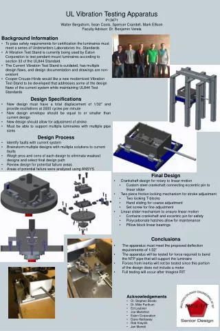
Download

1 / 27
270 likes | 421 Views
Systems Level Design Review UL Vibration Test Apparatus. January 11, 2013 KGCOE Room # 2255 10:00AM-12:00PM Est. Project & Team Information. Project: UL Vibration Test Apparatus Project Number: 13471 Customer: Eaton Corporation (previously Cooper Crouse-Hinds Industries)

E N D
Systems Level Design ReviewUL Vibration Test Apparatus January 11, 2013 KGCOE Room # 2255 10:00AM-12:00PM Est.
Project & Team Information Project: UL Vibration Test Apparatus Project Number: 13471 Customer: Eaton Corporation (previously Cooper Crouse-Hinds Industries) Customer Contact: Joe Manahan RIT Faculty Guide: Dr. Benjamin Varela Project Team: Walter Bergstrom Sean Coots Spencer Crandell Mark Ellison UL Vibration Test Apparatus
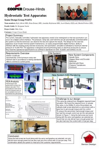
Project Background • Cooper Crouse-Hinds develops luminaires that are used in hazardous environments where ignition or explosion can have catastrophic consequences. • To pass safety requirements for certification the luminaires must meet a series of Underwriters Laboratories Inc. Standards. • A Vibration Test Stand is currently being used by Cooper Crouse-Hinds to test pendant mount luminaires according to section 33 of the UL844 Standard. • The Current Vibration Test Stand is outdated, has multiple design flaws, and design documentation and drawings are non-existent. • Cooper Crouse-Hinds would like a new Modernized Vibration Test Stand to be developed that addresses some of the design flaws of the current system while maintaining UL844 Test Standards. This new Design must also have a LabView interface and control capability integrated into the system. UL Vibration Test Apparatus
Design Goals over Winter/Spring MSD Note: It has been decided that this apparatus will be developed in multiple Senior Design Sequences. • Provide customer with two design concepts for vibration mechanism • One of the two designs must be an eccentric shaft mechanism while the customer is open to considering other design alternatives. • After discussing benefits and costs of the designs in this Systems Level Design Review, the Customer will decide on the vibration mechanism to be developed further. • Develop a final design of the vibration mechanism. • Design a steel test frame that will support the vibration mechanism and the vertical conduit. • Design but do not develop steel frame for entire vibration test machine. • Develop a full set of engineering drawings. • Calculate and select the required drive train system components. • Purchase materials, machine components, and assemble the vibration mechanism and test frame. • Test the mechanism to ensure that it meets 1/32” deflection requirement UL Vibration Test Apparatus
Summary of UL844 Vibration Test Standard LUMINAIRES FOR USE IN HAZARDOUS (CLASSIFIED) LOCATIONS – UL 844 Section 33 – Vibration Test Standards • Luminaire is to be subjected to 35 hours of vibration testing. • Luminaire assembly is to be attached to a 26-1/2” long conduit via NPT threading. The other end of the NPT threaded pipe is to be secured to the hub of a rigid mounting frame so that the conduit hangs vertically. The conduit should correspond to the smallest size of threaded conduit hub that is designed to attach to the Luminaire being tested. • The horizontal force to be applied to the system in order to obtain the deflection must me located 4” above the location of the conduit where the Luminaire attaches. • The deflection must be 1/32” with 1/16” total deflection per cycle. • The system must run at 2000 cycles/min. UL Vibration Test Apparatus
Force Applied to Deflect Luminaire Equations of relative motion were applied to derive the acceleration of the desired deflection assuming a constant angular velocity of the primary shaft. The moment of inertia was than approximated for the conduit with 100lbf cylinder at its end. Assuming the system acted as a pendulum and using the moment of inertia and acceleration we acquired a force. This was then superimposed with the force needed to bend the conduit (cantilever pipe) to the proper deflection. The calculated force was approximately 400lbf. UL Vibration Test Apparatus
UL844 Vibration Test Standard UL Vibration Test Apparatus
Design Flaws Associated with Current Design • Difficult for one technician to set up test • Lubricant not contained • Machine components exposed to contaminants • Belts used (slipping) • Uses single speed motor with a speed reducer • Frequency adjustment dial held in place with rope • No displacement adjustment • Attachment collar may experience minor buckling • Does not accounted for part wear and tolerance stack up UL Vibration Test Apparatus
Rotational to Linear Motion Mechanism • Options: • Eccentric Shaft • Crankshaft Variation for Adjustment Capabilities • Scotch Yoke • Variation for Adjustment Capabilities? • Cam Follower Rotational Input at 2000 rpm Output Linear Motion to Slider Mechanism • Allows for design of a single motor input and slider output mechanism for either the eccentric shaft or scotch yoke design • Slight adjustments to frame required for each case due to the orientation of the motor (either horizontal or vertical) UL Vibration Test Apparatus
Functional Decomposition (Page 1 of 2) Continued (next slide) UL Vibration Test Apparatus
Functional Decomposition (Page 2 of 2) UL Vibration Test Apparatus
Pillow block bearings • Notes: • Ranked from top to bottom, best to worst • Need to ask exactly what mechanism the current design employs • Issue is lubrication and lubrication containment if bearings are not used Linear bearing with rails Slider Mechanism Roller bearings w/ wheels Full fluid boundary w/ lubricant Magnetic UL Vibration Test Apparatus
Eccentric Shaft • Notes: • Ranked from top to bottom, best to worst • Also a linear motor option that does not fall under this category but still converts electrical energy to mechanical Scotch Yoke Rotational to Linear Mechanism Crankshaft Cam Follower Screw Actuator UL Vibration Test Apparatus
PUGH Matrix: Rotational to Linear Motion Mechanism UL Vibration Test Apparatus
Option 1 Eccentric Shaft(Custom Purchase) Eccentric Shaft • Notes: • Current design in use at Cooper • Simple design • No adjustment capability • Eccentric shafts expensive to purchase • Relatively few moving parts • Lubrication of connecting rod must be further studied Shaft Bearing(s)(Purchase) Connecting Rod(Custom) Connecting Rod Bearing(Purchase) Shims(Purchase) **Note: Green boxes denote optional design components UL Vibration Test Apparatus
Gear (Purchase) Option 2 Rotary Disc (Custom) Key (Purchase) Scotch Yoke Shaft (Purchase) • Notes: • Alternate design • Fairly simple • Adjustment capability • Lubrication of system must be further studied Yoke Plate (Custom) Pin (Purchase) Connection to Slider Mechanism (Custom) May be directly built into design **Note: Green boxes denote optional design components
Scotch Yoke CAD Concept UL Vibration Test Apparatus
PUGH Matrix: Slider Mechanism UL Vibration Test Apparatus
PUGH Matrix: Displacement Adjustment Mechanism UL Vibration Test Apparatus
Cost Analysis UL Vibration Test Apparatus
Risk Assessment UL Vibration Test Apparatus
Project Schedule (Page 1 of 2) Continued (next slide) UL Vibration Test Apparatus
Project Schedule (Page 2 of 2) UL Vibration Test Apparatus
Suggested Design Implementation • Scotch Yoke Design • Linear Bearings on Rails • Pivot Cam for Eccentric Adjustment Mechanism • AC Motor with Adjustment • Redesigned Flange Platform UL Vibration Test Apparatus
Open Discussion • Any questions? • Design concerns not discussed? • Feed back on work done to this point? • Feed back on method for calculating deflection force? • Follow-up meeting needed? • Customer decision on Vibration Mechanism UL Vibration Test Apparatus