Download
1 / 69
690 likes | 886 Views
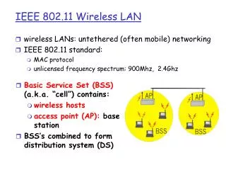
IEEE 802.11 Wireless LAN. Why Wireless LAN?. Traditional LANs need wires, which may be difficult to set up in some situations. Advantages of Wireless LANs Allow mobility and flexibility Reduced cost Applicable scenarios Offices Building with open area Hybrid with wired LANs.

E N D
Why Wireless LAN? • Traditional LANs need wires, which may be difficult to set up in some situations. • Advantages of Wireless LANs • Allow mobility and flexibility • Reduced cost • Applicable scenarios • Offices • Building with open area • Hybrid with wired LANs
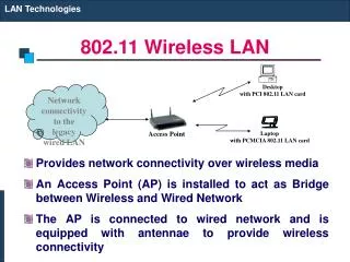
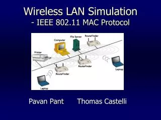
Architectures Infrastructure mode Infrastructure-less/ distributed/ad-hoc mode
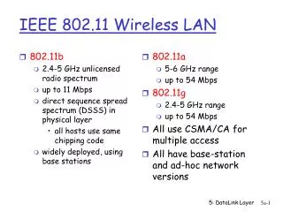
Physical Layer • RF: Spread Spectrum, no licensing required. Resistance to interference • Band: 915-Mhz, 2.4 GHz (worldwide ISM), 5.2 Ghz • Direct sequence spread spectrum (DSSS) • broaden the signaling band by artificially increasing the modulation rate using a spreading code. 2M or 10M. • Frequency hopping spread spectrum (FHSS) • hop from narrow band to narrow band within a wide band, using each narrow band for a specific time period.
MAC Layer: Hidden Terminal Problem • Node B can communicate with A and C both • A and C cannot hear each other • When A transmits to B, C cannot detect the transmission using the carrier sense mechanism • If C transmits, collision will occur at node B A B C
A B C MCAC (Multiple Access with Collision Avoidance) • When node A wants to send a packet to node B, node A first sends a Request-to-Send (RTS)to A • On receiving RTS, node A responds by sending Clear-to-Send (CTS), provided node A is able to receive the packet • When a node (such as C) overhears a CTS, it keeps quiet for the duration of the transfer • Transfer duration is included in RTS and CTS both
A B C Reliability • Wireless links are prone to errors. High packet loss rate detrimental to transport-layer performance. • Mechanisms needed to reduce packet loss rate experienced by upper layers • When node B receives a data packet from node A, node B sends an Acknowledgement (Ack). • If node A fails to receive an Ack, it will retransmit the packet
IEEE 802.11 Wireless MAC • Distributed and centralized MAC components • Distributed Coordination Function (DCF) • Point Coordination Function (PCF)
A B C IEEE 802.11 DCF • Uses RTS-CTS exchange to avoid hidden terminal problem • Any node overhearing a CTS cannot transmit for the duration of the transfer • Uses ACK to achieve reliability • Any node receiving the RTS cannot transmit for the duration of the transfer • To prevent collision with ACK when it arrives at the sender • When B is sending data to C, node A will keep quite
Collision Avoidance • With half-duplex radios, collision detection is not possible • CSMA/CA: Wireless MAC protocols often use collision avoidance techniques, in conjunction with a (physical or virtual) carrier sense mechanism • Carrier sense: When a node wishes to transmit a packet, it first waits until the channel is idle • Collision avoidance: Once channel becomes idle, the node waits for a randomly chosen duration before attempting to transmit
Congestion Avoidance • When transmitting a packet, choose a backoff interval in the range [0,cw] • cw is contention window • Count down the backoff interval when medium is idle • Count-down is suspended if medium becomes busy • When backoff interval reaches 0, transmit RTS
B1 = 25 B1 = 5 wait data data wait B2 = 10 B2 = 20 B2 = 15 Example B1 and B2 are backoff intervals at nodes 1 and 2 cw = 31
IEEE 802.11 PCF • Purpose: contention-free data transmission • System components • Access Point (AP): a coordinator controlling the medium access in a poll-and-response manner • Stations: transmit only when being polled • A LAN operates in PCF or DCF mode • The duration in which PCF operates is called contention-free period (CFP) • Before/after a CFP, the network operates in DCF.
IEEE 802.11 PCF • Starting • AP seizes the medium by using “priority inter-frame space” (PIFS) • AP sends out a beacon packet to announce the beginning of a CFP (the packet contains the duration of the CFP) • In a CFP • AP may transmit data packets to any station • AP may send a polling packet to a station • The polled station replies with a data packet or a NULL packet (when nothing to send) • Ending • AP sends out an END packert.
MAC Management • Synchronization • finding and staying with a WLAN. • Synchronization functions • Power management • sleeping without missing any messages • power management functions, e.g., periodic sleep, frame buffering, traffic indication map • Association and Re-association • joining a network, roaming, moving from one AP to another, scanning
Power Management • 802.11 power off station during idle periods • A station can be in one of three states: • transmitter on, • receiver only on, • dozing: both transmitter and receivers off • is transparent to existing protocols • is flexible to support different application
Power Management • APs buffer packets for sleeping stations • AP announces which stations have frames buffered • traffic indication map (TIM) sent with every beacon. • All multicasts/broadcasts are buffered • Time Synchronization Function (TSF) assures AP and power save stations are synchronized • stations wake up periodically to hear a beacon • TSF timer keeps running when stations are sleeping • synchronization allows extreme low power operation
Summary • Architectures of Wireless LANs • Infrastructure or infrastructure-less • MAC • Hidden terminal problem • collision avoidance • DCF and PCF • MAC management • Power management and others
What is a MANET (Mobile Ad Hoc Networks)? • Formed by wireless hosts which may be mobile • No pre-existing infrastructure • Routes between nodes may potentially contain multiple hops • Nodes act as routers to forward packets for each other • Node mobility may cause the routes change B A A B C C D D
Why MANET? • Advantages: low-cost, flexibility • Ease & Speed of deployment • Decreased dependence on infrastructure • Applications • Military environments • soldiers, tanks, planes • Civilian environments • vehicle networks • conferences / stadiums • outside activities • Emergency operations • search-and-rescue / policing and fire fighting
Challenges • Collaboration • Collaborations are necessary to maintain a MANET and its functionality. • How to collaborate effectively and efficiently? • How to motivate/enforce nodes to collaborate? • Dynamic topology • Nodes mobility • Interference in wireless communications
Routing Protocols: Overview • Proactive protocols • Determine routes independent of traffic pattern • Traditional link-state and distance-vector routing protocols are proactive • Examples: • DSDV (Dynamic sequenced distance-vector) • OLSR (Optimized Link State Routing) • Reactive protocols • Maintain routes only if needed • Examples: • DSR (Dynamic source routing) • AODV (on-demand distance vector) • Hybrid protocols • Example: Zone Routing Protocol (intra-zone: proactive; inter-zone: on-demand)
Routing Protocols: Tradeoff • Latency of route discovery • Proactive protocols may have lower latency since routes are maintained at all times • Reactive protocols may have higher latency because a route from X to Y may be found only when X attempts to send to Y • Overhead of route discovery/maintenance • Reactive protocols may have lower overhead since routes are determined only if needed • Proactive protocols can (but not necessarily) result in higher overhead due to continuous route updating • Which approach achieves a better trade-off depends on the traffic and mobility patterns
Dynamic Source Routing • J. Broch, D. Johnson, and D. Maltz, “The dynamic source routing protocol for mobile ad hoc networks,” Internet-Draft Version 03, IETF, October 1999. • When node S wants to send a packet to node D, but does not know a route to D, node S initiates a routing process • Runs in three phases • Route Discovery Route Reply Path Establishment • Route Discovery • Source node S floods Route Request (RREQ) • Each node appends own identifier when forwarding RREQ
Route Discovery in DSR Y Z S E F B C M L J A G H D K I N Represents a node that has received RREQ for D from S
Route Discovery in DSR Y Broadcast transmission Z [S] S E F B C M L J A G H D K I N Represents transmission of RREQ [X,Y] Represents list of identifiers appended to RREQ
Route Discovery in DSR Y Z S [S,E] E F B C M L J A G [S,C] H D K I N
Route Discovery in DSR Y Z S E F [S,E,F,J] B C M L J A G H D K I N [S,C,G,K]
Route Reply in DSR • Destination D on receiving the first RREQ, sends a Route Reply (RREP) • RREP is sent on a route obtained by reversing the route appended to received RREQ • RREP includes the route from S to D on which RREQ was received by node D
Route Reply in DSR Y Z S RREP [S,E,F,J,D] E F B C M L J A G H D K I N Represents RREP control message
Route Reply in DSR • Node S on receiving RREP, caches the route included in the RREP • When node S sends a data packet to D, the entire route is included in the packet header • Hence the name source routing • Intermediate nodes use the source route included in a packet to determine to whom a packet should be forwarded
Data Delivery in DSR Y Z DATA [S,E,F,J,D] S E F B C M L J A G H D K I N Packet header size grows with route length
Some Other Routing Protocols • Location information aided protocols • Power-aware protocols • Others … • e.g., considering the stability of topology
Location-Aided Routing (LAR) • Y. Ko and N. Vaidya, “Location-aided routing (LAR) in mobile ad hoc networks,” MobiCom'98. • Exploits location information to limit scope of route request flood • Location information may be obtained using GPS • Expected Zone is determined as a region that is expected to hold the current location of the destination • Expected region determined based on potentially old location information, and knowledge of the destination’s speed • Route requests limited to a Request Zonethat contains the Expected Zone and location of the sender node • B. Karp, and H. Kung, “Greedy Perimeter Stateless Routing for Wireless Networks,” MobiCom 2000.
Power-Aware Routing • Modification to DSR to make it power aware (for simplicity, assume no route caching): • Route Requests aggregate the weights of all traversed links • Destination responds with a Route Reply to a Route Request if • it is the first RREQ with a given (“current”) sequence number, or • its weight is smaller than all other RREQs received with the current sequence number
Geography Adaptive Fidelity • Each node associates itself with a square in a virtual grid • Node in each grid square coordinate to determine who will sleep and how long [Y. Xu, et al. “Geography Adaptive Fidelity in Routing,” Mobicom’2001] Grid head
Research in Other Layers • Transport layer • A survey: A. Hanbali, E. Altman, P. Nain, “A Survey of TCP over Mobile Ad Hoc Networks (2004)”. • Application layer • Data management • e.g., B. Xu, A. Ouksel, and O. Wolfson, "Opportunistic Resource Exchange in Inter-vehicle Ad Hoc Networks," MDM, 2004. • Distributed algorithms • clock synchronization • mutual exclusion • leader election • Byzantine agreement
Problems • Hosts may misbehave or try to compromise security at all layers of the protocol stack • Transport layer: securing end-to-end communication • Need to know keys to be used for secure communication • May want to anonymize the communication • Network layer: misbehaving hosts may create many hazards • May disrupt route discovery and maintenance:Force use of poor routes (e.g., long routes) • Delay, drop, corrupt, misroute packets • May degrade performance by making good routeslook bad • MAC layer: misbehaving nodes may not cooperate • Disobey protocol specifications for selfish gains • Denial-of-service attacks
Security in MANET: Agenda • Key management • Securing communications • Dealing with MAC and Network layer misbehaviors
Key Management • Challenges • In “pure” ad hoc networks, access to infrastructure cannot be assumed • Network may also become partitioned • Solutions • Distributed public key infrastructure • Self-organized key management • Distributed key certification • TESLA • Others
Self-Organized Public Key Management [Capkun03] • Nodes form a “Certificate Graph” • each vertex represents a public key • an edge from Ku to Kw exists if there is a certificate signed by the private key of node u that binds Kw to the identity of some node w. Ku (w,Kw)Pr Ku Kw
Self-Organized Public Key Management [Capkun03] • Four steps of the management scheme • Step 1: Each node creates its own private/public keys. Each node acts independently
Self-Organized Public Key Management [Capkun03] • Step 2: When a node u believes that key Kw belongs to node w, node u issues a public-key certificate in which Kw is bound to w by the signature of u • u may believe this because u and w may have talked on a dedicated channel previously • Each node also issues a self-signed certificate for its own key • Step 3: Nodes periodically exchange certificates with other nodes they encounter • Mobility allows faster dissemination of certificates through the network
Self-Organized Public Key Management [Capkun03] • Step 4: Each node forms a certificate graph using the certificates known to that node Authentication: When a node u wants to verify the authenticity of the public key Kv of node v, u tries to find a directed graph from Ku to Kv in the certificate graph. If such a path is found, the key is authentic.
Self-Organized Public Key Management [Capkun03] • Misbehaving hosts may issue incorrect certificates • If there are mismatching certificates, indicates presence of a misbehaving host (unless one of the mismatching certificate has expired) • Mismatching certificates may bind same public key for two different nodes, or same node to two different keys • To resolve the mismatch, a “confidence” level may be calculated for each certificate chain that verifies each of the mismatching certificates • Choose the certificate that can be verified with high confidence – else ignore both certificates
Secure Communication • With the previously discussed mechanisms for key distribution, it is possible to authenticate the assignment of a public key to a node • This key can then be used for secure communication • The public key can be used to set up a symmetric key between a given node pair as well • TESLA provides a mechanism for broadcast authentication when a single source must broadcast packets to multiple receivers
Secure Communication • Sometimes security requirement may include anonymity • Availability of an authentic key is not enough to prevent traffic analysis • We may want to hide the source or the destination of a packet, or simply the amount of traffic between a given pair of nodes
Traffic Analysis • Traditional approaches for anonymous communication, for instance, based on MIX nodes or dummy traffic insertion, can be used in wireless ad hoc networks as well