Download
1 / 32
400 likes | 760 Views
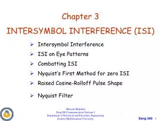
Inter-symbol interference ISI. Up to this moment we have studied the effect of AWGN on baseband pulse transmission The next source of bit error in baseband pulse transmission is the ISI which will be considered in details in this section. General model of digital communication system.

E N D
Inter-symbol interference ISI Up to this moment we have studied the effect of AWGN on baseband pulse transmission The next source of bit error in baseband pulse transmission is the ISI which will be considered in details in this section
General model of digital communication system Consider the general model for the digital communications shown below As the input binary data travels from the transmitter to the receiver it passes through three filters, transmit filter , channel and the receive filter
Received signal formula The receiver filter output is given by Where is a scaling factor and represent the overall system impulse response which is given by
Frequency response We assume that the system impulse response is normalized by setting The overall system impulse response in frequency domain can be found by taking the Fourier transform of which results in
Principle of operation of the receiver The receiver filter output is sampled at time , therefore
The term represent the contribution of the transmitted bit (desired bit) The term represent the residual effect of all other transmitted bits (ISI) on the decoding of the bit In the absence of both ISI and noise, the sampled output will be only
Situation where only the ISI will be considered and AWGN can be neglected When the signal to noise ratio is high, as in the telephone system, the operation of the system is largely limited by ISI rather than AWGN noise
Nyquist’s criterion for distortion less base band binary transmission In order to eliminate the ISI completely we need the residual effects from all symbols on the symbol to be zero at the sampling instant Also we need the output of the sampler to be at he sampling instant when This means that the term
Derivation of the system transfer function If we take the Fourier transform of the previous equation, then we have The Fourier transform of an infinite periodic sequence of delta functions of period , whose individual areas are weighted by the respective sample values of Is given by
Fourier transform of Where When , therefore
Fourier transform of When , therefore which means that
The final equation to obtain Now the system transfer function can be derived from the equation presented in slide 9
Ideal Nyquist channel The Nyquist criterion for distortion-less baseband transmission in the absence of AWGN noise states that the frequency function of the channel eliminates inter-symbol interference for samples taken at intervals provided that it satisfies
Ideal Nyquist channel In order to satisfy the equation, , the frequency function must be in the form of a rectangular function given by Or
Ideal Nyquist channel The overall system bandwidth appears in equation is defined as The special value of the bit rate is called the Nyquist rate and is called the Nyquist bandwidth
Ideal Nyquist channel The system impulse response which can be obtained by taking the inverse Fourier transform of
If digital binary bits are passed through a pulse shape filter, all the bits takes then the received samples at are ISI free as shown below
Practical difficulties in ideal Nyquist channel • There are two practical difficulties that make it undesirable objective for system design • It require an ideal low pass filter characteristics in frequency domain which is physically impossible • The function decreases as for large which results in slow decay rate of the side lobes (tails)
Practical difficulties in ideal Nyquist channel If there is a small timing error (called jitter error) between the transmitter and the receiver, this will results in a significant ISI interference which may leads to errors in the decoded bits at the receiver The more practical solution is to design the channel transfer function based on the raised cosine spectrum which is discussed next
Raised cosine spectrum In the raised cosine, the frequency response of the channel is designed according to
Raised cosine The frequency parameter and the bandwidth are related by The parameter is called the roll off factor The roll factor indicates the excess bandwidth over the ideal Nyquist bandwidth
Raised cosine The transmission bandwidth, , is defined by If , then the transmission bandwidth is which is the Nyquist bandwidth If , then the transmission bandwidth is which is equal twice the Nyquist bandwidth If , then transmission has to be at a lower bit rate to avoid ISI
Graphical representation of the channel transfer function The frequency response normalized by multiplying it by is shown below for different values of the roll off factor
The time domain( impulse response) of the raised cosine function The impulse (time) response is obtained by taking the inverse Fourier transform of the frequency response The function is plotted in graphically in the next slide
Notes about • The time response consists of the product of two factors • which ensures the zero crossing of at the desired sampling instant • reduces the tails of the pulses considerably below that obtained from the ideal Nyquist channel (for ideal Nyquist channel)
Notes about The special case with is known as the full cosine rolloff characteristics Under this condition the transmission bandwidth is given by
Summery ISI is a major source of bit error which degrades the communication system performance ISI occurs due to the dispersive nature of the communication channel ISI can be eliminated by transmitting the symbols (bits) at a rate equals the Nyquist rate in an ideal Nyquist channel
Summery A pulse shape filter can be used in the transmitter to reshape the pulses before the bits are transmitted A commonly used filter is the raised cosine filter The raised cosine filter overcome the practical difficulties associated with the ideal Nyquist channel on the expense of requiring extra bandwidth for transmission
Example 1 The bandwidth required for double side modulated carrier is given by