Download
1 / 33
330 likes | 509 Views
Compact Muon Solenoid Detector (CMS) & The Token Bit Manager (TBM). Alex Armstrong & Wyatt Behn Mentor: Dr. Andrew Ivanov. Part 1: The TBM and CMS. Understanding how the LHC and the CMS detector work as a unit Learning how the TBM is a vital part of the CMS detector

E N D
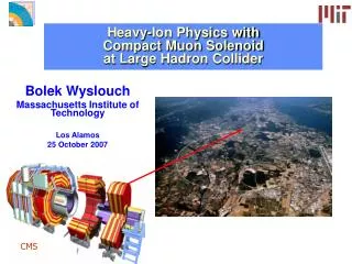
Compact Muon Solenoid Detector (CMS) & The Token Bit Manager (TBM) Alex Armstrong & Wyatt Behn Mentor: Dr. Andrew Ivanov
Part 1: The TBM and CMS • Understanding how the LHC and the CMS detector work as a unit • Learning how the TBM is a vital part of the CMS detector • Physically handling and testing the TBM chips in the Hi-bay
Motivation • The CMS detector requires upgrades to handle increased beam luminosity • Minimizing data loss in the innermost regions of the detector will therefore require faster, lighter, more durable, and more functional TBM chips than the current TBM 05a We tested many of the new TBM08b and TBM09 chips to guarantee that they meet certain standards of operation.
CERN Conseil Européen pour la Recherche Nucléaire (European Council for Nuclear Research) (1952) Image Credit:: http://home.web.cern.ch/
CERN -> LHC Large Hadron Collider (2008) 1) ATLAS 2) ALICE 3) LHCb 4) CMS Two proton beams travel in opposite directions until collision in detectors Image Credit: hep://home.web.cern.ch/topics/large-‐hadron-‐collider Image Credit: http://lhc-machine-outreach.web.cern.ch/lhc-machine-outreach/collisions.htm
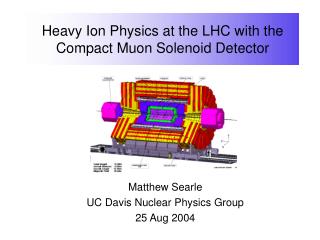
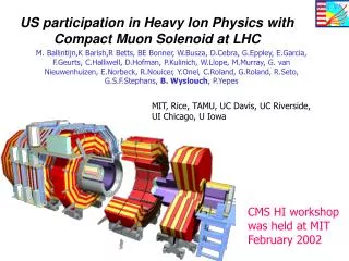
CERN -> LHC -> CMS Compact Muon Solenoid (2008) Image Credit: hep://cms.web.cern.ch/ Image Credit: http://home.web.cern.ch/about/experiments/cms
CMS Detector System Image Credit: hep://home.web.cern.ch/about/experiments/cms
Inner Silicon Tracker Semiconductor detector technology used to measure and time stamp position of charged particles Inner layers consist of pixels for highest possible resolution Outer layers consist of strips for lower production cost Image Credit: https://inspirehep.net/record/1234410/plots
Inner Silicon Pixel Tracker The layers consist of individual pixels grouped into modules managed by the TBMs Pixel layers provide the highest resolution data for positions of charged particle Image Credit: CMS CR -2011/256
Inner Silicon Pixel Tracker Image Credit: http://www.hep.ph.ic.ac.uk/~hallg/Pix_CMS/
Image Credit: hep://cms.web.cern.ch/news/cms-‐observes-‐hints-‐mel@ng-‐upsilon-‐par@cles-‐lead-‐nuclei-‐collisions
Problems & Solutions 1) SO MUCH DATA! - 40 terabytes/second • Level 1 trigger system (3500ns latency) • Higher level trigger system 2) High Collision Rate - 40 MHz (25ns gap) • Buffer zones in ROCs • High time resolution
Level 1 Trigger • Completely Automatic - No Software • Selects ~1/10,000 hits • The Selection Process: 1) Detection by Calorimeter and Muon Chambers 2) Trigger Electronics selects desirable events 3) Acceptance/rejection trigger sent toTBM 4) TBM sends message to ROC to collect or discard 5) Collected messages are sent downstream
From Scatta to Data Particles Data Signal Trigger Signal
What Makes A Module? • The ROCs are the base for the silicon pixel sensor • The TBM is integrated directly onto the circuit above the sensor • 3 layers of pixel detectors will form the Inner Tracking Level Image Credit: hep://arxiv.org/pdf/1001.3933.pdf
The Pixels/ROC Data Storage • Each silicon sensor is only 150 x 100 μm (about 2 hair widths) • The ROCs keep their time-stamped information until they are cleared to release to the data stream • The Inner Tracking Detector has approx 48 million pixels Image Credit: hep://cms.web.cern.ch/news/silicon-‐pixels
Pixel Detectors/Modules • The TBM chip (shown below) is used to manage ROC’s data release and reset ROCs TBM • [This picture displays a TBM connected to 16 ROC (read out chips)] 3.2 mm 4.78 mm Image Credit: hep://arxiv.org/Hp/arxiv/papers/0707/0707.1026.pdf
The TBM and Token Passing • The TBM uses a “token” to control and convey information to the ROCs • The token is also used by the TBM to register the state of each ROC • TBMs send tokens through the ROCs before acquiring data, if the token is not returned to the TBM in a certain time interval, the event is labeled a “No Token Pass” and the ROCs clear their data buffers • The TBMs are a direct line of communication between the detector and the LHC operators above CMS
Hardware & Calibration • Using Cascade Probe Station and Nucleus 3.2 Interactive Software • The stage (or chuck) moves freely beneath a stationary testing board that contains a probing zone • The wafer is placed on the chuck and raised up to the board to make a connection and run tests (Note: Only 50 μm of freeplay are allowed when making connection) • Some issues with the chuck being unbalanced could lead to crashing the probe
Putting on a Single TBM Chip ~1.6 cm
Testing Wafers • Contain thousands of TBM chips • 200 mm diameter wafer with 3 different types of TBM chips on it
Making Contact Scratches Indicate Clear Contact
Running the Test Code Interface Header GUI Headers Reference Library for Code
Summary of New TBM Benefits • TBM 09 is digital, whereas the current version is analog (TBM 05a) • The TBM 09 uses two TBM 08b cores that it splits between the ROCs, this allows for a more precise control when analyzing malfunctions • Because the ROCs are distributed, the control room can reset certain ROCs without resetting a whole module (this is good for testing issues) • The TBM 09 is more radiation resistant and also has the benefit of being made of less material which interferes with possible particle detection far less
Part 2: Coding • Work with the programming language of C++ • Using the data analysis framework ROOT to interpret simulated data • Using these two in tandem to create small programs that create useful interpretations of data
Analyzing the Data Data analysis framework used to effectively store, recall, and analyze the large amounts of data output by the LHC
Data Analysis - Simulation • Simulated data is used to show how possible particle collisions and outcomes may play out • Simulations also help to show discrimination between theory and experimental result • Comparing theoretical vs. experimental allows us to look for new and exciting things
Signal vs. Background - Ex. • This is an example of the total energy of a top anti-top particle creation event • The green background is clearly different from the blue signal information