Download

1 / 54
540 likes | 790 Views
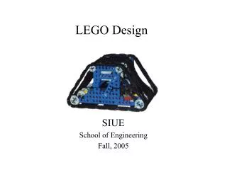
LEGO Design. SIUE School of Engineering Fall, 2005. Goals:. Build better robots Minimize mechanical breakdowns Build robots that are easy to control Encourage good design strategy. Geometry. Three plates = 1 brick in height.

E N D
LEGO Design SIUE School of Engineering Fall, 2005
Goals: • Build better robots • Minimize mechanical breakdowns • Build robots that are easy to control • Encourage good design strategy
Geometry • Three plates = 1 brick in height • 1-stud brick dimensions: exactly5/16” x 5/16” x 3/8” (excluding stud height 1/16”), • This is the base geometry for all LEGO components
Structure • Common pitfall when trying to increase mechanical robustness:
Structure • The right way:
Structure • The right way:
A good robot starts with a good foundation. A robot whose body is not structurally sound will be fraught with problems for the designers. The first and most important is that the friction between stacked bricks should not be relied upon for structural strength. We recommend using connector pegs to help create a "skeleton" like the one below. A design like this is both light and strong but usually requires a number of rebuilds to get perfect.
Structural supports like the ones shown below can be placed on almost any chassis design. Use this to your advantage. You can get by with fewer legos and have a stronger chassis this way
The picture below demonstrates a very structurally sound way of constructing a frame with legos. The 3 wide connector peg can be used for one of the 3 join points, or an additional 4x1 brick can be used.
The structure below demonstrates a very strong design that will not come apart unless you take it apart.
Connector pegs • Black pegs are tight-fitting for locking bricks together. • Grey pegs turn smoothly in bricks for making a pivot
Drivetrain 40T • LEGO Gears 8T 16T Bevel 1T Worm 24T 24T Crown
Radius, Torque, and Force on a Gear torque = r x F
Since the forces between the teeth of the two gears are equal in magnitude but act opposite in directions, the torque exerted on the right axle is three times the torque exerted on the left axle (sincethe radii of thee gears differ by a factor of three). Thus this gear system as acts as a “torque converter”, increasing the torque at the expense of decreasing the rate at which the axle turns.
The torque at the “output shaft” is 9 times the torque provided on the left(‘input”) axle. The output shaft will of course spin 9 times slower than the input shaft, but it will be much harder to stall. Have someone grab the output shaft and try to “stall” your fingers as you spin the input axle. It’s not that easy!
Worm Gears 3 • Pull one tooth per revolution 1 2 • Result is a 24:1 gearbox 4
Differential Drive The differential gear is used to help cars turn corners. The differential gear (placed midway between the two wheels) allows one wheel to turn at a greater speed than the other. Even though the wheels may be turning at different speeds, the action of the differential means that the torque generated by the motor is distributed equally between the half-axles upon which the wheels are mounted. Assuming the robot's weight is sufficient and distributed properly, the robot should be able to turn with its drive motors at full power without causing either wheel to slip.
Motors • 9V Gear Motor • ~ 150 mA • 300 RPM (no load) • Polarity
Motors • 9V Micro Motor • 20-30 RPM
Mounting Motors Note Bulge under motor
Mounting Motors • Add a gear:
This shows an interesting way to mount a photoresistor, as well as how to sheild it from a dedicated light source.
Spin x-y-z See more examples at http://constructopedia.media.mit.edu/
Build for good control • Slow vs. fast? • Gear backlash • Stability • Skidding (Tank-tracks vs. wheels) • Differential Steering !!!