Download
1 / 47
470 likes | 486 Views
Learn about the principles and applications of pneumatic systems, including air compressors, air receivers, fluid conditioners, pressure control valves, and pneumatic actuators.

E N D
Chapter 13 Pneumatics: Air Preparation and components
Learning Objectives Upon completing this chapter, you should be able to: 1. Apply the perfect gas laws to determine the interactions of pressure, volume, and temperature of a gas. 2. Describe the purpose, construction, and operation of compressors. 3. Calculate the power required to drive compressors to satisfy system requirements. 4. Determine the size of compressor air receivers for meeting system pressure and flow-rate requirements. 5. Explain the purpose and operation of fluid conditioners, including filters, regulators, lubricators, mufflers, and air dryers. 6. Calculate pressure losses in pneumatic pipelines. 7. Perform an analysis of moisture removal from air using aftercoolers and air dryers. 8. Determine how the flow rate of air can be controlled by valves. 9. Describe the purpose, construction, and operation of pneumatic pressure control valves, flow control valves, and directional control valves. 10. Discuss the construction and operation of pneumatic cylinders and motors. 11. Determine the air-consumption rate of pneumatically driven equipment.
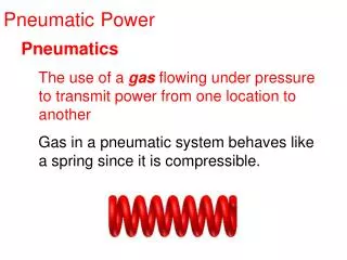
What are Pneumatic systems? It Pneumatic systems use pressurized gases to transmit and control power? Why do we use pneumatic systems instead of hydraulic ones? • Air exhibit smaller inertia than do liquids . • Air exhibit smaller viscosity than do liquid. • friendly media • pneumatic systems are less expensive than hydraulic systems. Limitations : it is impossible to obtain precise, controlled actuator velocities with pneumatic systems. Pressure -Pneumatic pressures are quite low due to explosion dangers involved if components such as air tanks should rupture (less than 250 psi) - Hydraulic pressures can be as high as 12,000 psi.
Components of pneumatic system Essentially the following six basic components are required for pneumatic systems: 1. Air generation and distribution unit which consist of the following parts a. An air tank to store a given volume of compressed air b. A compressor to compress the air that comes directly from the atmosphere c. An -electric motor or other prime mover to drive the compressor d. Air filter e. Air dryer f. Air lubricator g. pressure and flow regulators 2. Piping to carry the pressurized air from one location to another 3. Valves to control air direction, pressure, and flow rate 4. Actuators 5.The sensors and transducers 6. The system display, physical magnitude measurement, and control devices
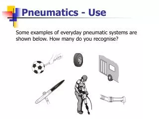
Industrial Applications - stamping -drilling - hoisting -punching - clamping -assembling - riveting - materials handling -logic controlling operations.
PROPERTIES OF AIR • .The reference point is sea level, where the atmosphere exerts a pressure of 14.7 psia (101 kPa abs). • When making pneumatic circuit calculations, atmospheric pressure of 14.7 psia is used as a standard. The corresponding standard specific weight value for air is 0.0752 lb/ft3 at 14.7 psia and 68°F (11.8 N/m3 at 101 kPa abs and 20°C). • when making pneumatic circuit calculations, the term standard air is used. Standard air is sea-level air having a temperature of 68°F, a pressure of 14.7 psia (20°C and 101 kPa abs), and a relative humidity of 36%. Air elements 21% oxygen 78% nitrogen 1% other gases up to 4% water vapor
Use of Compressed Air • compressors are used to compress and supply the necessary quantities of air. Compressors are typically of the piston, vane, or screw type. • Basically, a compressor increases the pressure of a gas by reducing its volume as described by the perfect gas laws. • Pneumatic systems normally use a large centralized air compressor, which is considered to be an infinite air source similar to an electrical system where you merely plug into an electrical outlet for electricity. • Free air from the atmosphere contains varying amounts of moisture. This moisture can be harmful in that it can wash away lubricants and thus cause excessive wear and corrosion. Hence, in some applications, air dryers are needed to remove this undesirable moisture. • Since pneumatic systems exhaust directly into the atmosphere, they are capable of generating excessive noise. Therefore, mufflers are mounted on exhaust ports of air valves and actuators to reduce noise and prevent operating personnel from possible injury, resulting not only from exposure to noise but also from high-speed airborne particles.
THE PERFECT GAS LAWS Boyle’s Law (A constant-temperature process)
Charles’ Law (A constant-pressure process.)
Gay-Lussac’s Law (A constant-Volume process)
Piston Compressor • There are three types of Reciprocating Piston Compressor - It operates very much like an internal combustion engine. Air enters through an intake valve, is compressed, and exits through an exhaust valve Range of pressure Single stage Up to 400kPa (4bar/58psi) double stage Up to 1500kPa (15bar/217.5psi) Trebel or multi stage Over 1500kPa (15bar/217.5psi)
Single stage Reciprocating Piston Compressor Operation Air is drawn in through input valve during the intake stroke and compressed during the compression stroke Advantages -Safety and reliability - Available in different versions and pressure ranges and volume flow Disadvantages -heat loses because of high pressure • Economical only for pressure from 8-10 bar for small deliveries and up to 4 deliveries for large deliveries Multiple stage Reciprocating compressor • A smaller pressure difference per stage is chosen • Air is cooled between stages
Screw type compressor -it is a rotary compressor with two shafts • It works according to displacement principle • It deliveries continuous pressure (no pulsation or fluctuation ) • No intake or exhaust valves • High power , little maintenance • Can be build as oil free device Single shaft rotary compressor Two shaft rotary compressor
Vane Rotary Compressor • It is a single shaft rotary compressor working according displacement principle • Intake and exhaust occur via the sliding vanes of an electrically mounted rotor which decrease the volume of compression chamber from intake to exhaust - The output has few pulsation
Diaphragm compressor - In the diaphragm compressor, the piston pushes against a diaphragm, so the air does not come in contact with the reciprocating parts . - This type compressor is preferred for food preparation, pharmaceutical, and chemical industries, because no effluent from the compressor enters the fluid.
Roots blower (Lobe compressor) or superchargers • It is operated without internal compression • It is often used when a positive displacement compressor is needed with high delivery volume but low pressure (typically 1-2 bar). - Operating pressure is mainly limited by leakage between rotors and housing. -it is possible for rotor to operates without contact, thus removing the need of lubrications - This type of compressor is mainly used for pneumatic conveying
Axial flow compressor • air is accelerated to a high speed by rotors. • Air finally is passed though diffuser • Kinetic energy is converted to pressure • To reach high stage are connected in series Radial flow compressor • Kinetic energy is converted into pressure • The intake air is axial with air direction being changed and exhausted radial • Require little maintenance • Needs several stages to reach high pressure
Compressor selection Operation criteria - Working pressure • Volume • Type of compressed air Economic factor • Investment and depreciation • Installation • Space usage • Servicing and maintenance • Additional equipment
Compressed air filtration - A compressed air filter removes contaminants and water droplets from the air. - As compressed air enters the filter bowl, it is forced to flow through the guide slots in the baffle plate . • As it makes the u-turn, the particles are centrifuged out and collect in the lower part of the filter bowl. • Condensate that collects in the bowl must be drained periodically. • The filter has a manual drain or automatic drain. In-line filters contain filter elements that remove contaminants in the 5- to 50-m range.
Characteristics of Filters 1. size of particles they will stop (pore size) pore size: the minimum particle size which can be filtered out Particle size is measured in SI units of micrometres - Dust particles are generally larger than 10/m - Smoke and oil particles are around1 /m. - < 0.01/m particle size filter Microfilters with removable cartridges passing air from the centre to the outside of the cartridge case will remove 99.9% of particles down to 0.01/m, the limit of normal filtration. • Coarse filters, constructed out of wire mesh and called strainers, are often used as inlet filters. These are usually specified in terms of the mesh size 2. Degree of separation (efficiency) The percentage of particles of a particular size which can be separated out
Air Lubricators A lubricator ensures proper lubrication of internal moving parts of pneumatic components. Transformation oil into mist
Pneumatic Pressure Indicators - Pressure indicator that provides a two-color, two-position visual indication of air pressure. - The rounded lens configuration provides a 180° view of the indicator status, which is a fluorescent signal visible from the front and side. -The indicator is easily panel-mounted using the same holes as standard electrical pilot lights. Ranges 0.5 to 30 psi 25 to 150 psi 45 to 150 psi.
Pneumatic Silencers (muffler) A pneumatic exhaust silencer (muffler) is used to control the noise caused by a rapidly exhausting airstream flowing into the atmosphere.
Aftercoolers An aftercooler is a heat exchanger that has two functions. • it serves to cool the hot air discharged from the compressor to a desirable level (about 80 to 100°F) before it enters the receiver. • it removes most of the moisture from the air discharged from the compressor by virtue of cooling the air to a lower temperature.
Air Dryers Aftercoolers remove only about 85% of the moisture from the air leaving the compressor. Air dryers are installed downstream of aftercoolers when it is important to remove enough moisture from the air so that the air will not become saturated as it flows through the pneumatic system.
Air dryer The function of this device is to remove water vapor contains from compressed air 1. Drying by Cooling (low temperature drying) • The air is passed through a heat-exchanger system which a refrigerant flows • reducing the temperature of air to dew point (+2 ºC to +5 ºC) • The air is heated again to ambient temperature
- The lowest equivalent dew points (down to -90°C) can be achieved by means of adsorption drying. -In this process, the compressed air is passed through a gel and the water is deposited on the surface, i.e., it is adsorbed. ( Adsorb:water is deposited on the surface of solids.) -The drying agent is a granular material of sharp-edged shape or in bead form. -The drying agent consists almost entirely of silicon dioxide. -In practice, two tanks are used. When the gel in one tank is saturated, the air flow is switched to the dry, second tank and the first tank is regenerated by hot-air drying.
3. Absorption drying - It is a purely chemical process. -The moisture in the compressed air forms a compound with the drying agent in the tank. - This causes the drying agent to break down; it is then discharged in the form of a fluid at the base of the tank. - High cost and too low for efficiency most applications. -Oil vapour and oil particles are also separated in the absorption dryer. - Larger quantities of oil have an effect on the efficiency of the dryer, however. The features of the absorption process are: • Simple installation of the equipment • Low mechanical wear because there are no moving parts in the dryer • No external energy requirements.
AIR CONTROL VALVES Pressure Regulators
Directional Control Valves Two-Way Directional Control Valves
Pneumatic Rotary Actuators Axial piston air motor.