Download

1 / 22
220 likes | 386 Views
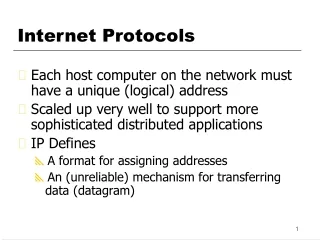
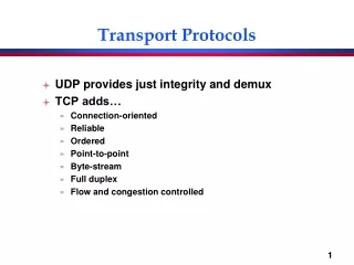
Ch. 7 : Internet Transport Protocols. Our goals: understand principles behind transport layer services: Multiplexing / demultiplexing data streams of several applications reliable data transfer flow control congestion control. Chapter 6: rdt principles Chapter 7: multiplex/ demultiplex

E N D
Ch. 7 : Internet Transport Protocols
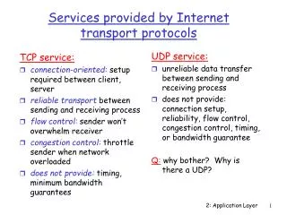
Transport Layer Our goals: understand principles behind transport layer services: Multiplexing /demultiplexing data streams of several applications reliable data transfer flow control congestion control Chapter 6: rdt principles Chapter 7: multiplex/ demultiplex Internet transport layer protocols: UDP: connectionless transport TCP: connection-oriented transport connection setup data transfer flow control congestion control Transport Layer 2
Transport vs. network layer • Transport layerusesNetwork layer services • adds more value to these services
Multiplexing & Demultiplexing
receive segment from L3deliver each received segment to correct socket gather data from multiple sockets, envelop data with headers (later used for demultiplexing), pass to L3 = socket = process application application application transport transport transport P3 P1 P2 P1 P4 network network network link link link physical physical physical Multiplexing at send host: Demultiplexing at rcv host: Multiplexing/demultiplexing host 3 host 2 host 1
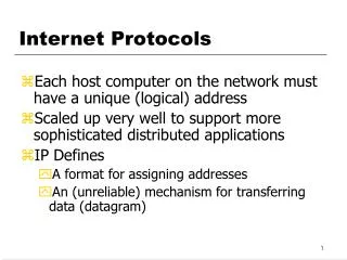
host receives IP datagrams each datagram has source IP address, destination IP address in its header each datagram carries one transport-layer segment each segment has source, destination port number in its header host uses port numbers, and sometimes also IP addresses to direct segment to correct socket from socket data gets to the relevant application process How demultiplexing works 32 bits source IP addr dest IP addr. L3 hdr other IP header fields source port # dest port # L4 header other header fields application data (message) appl. msg TCP/UDP segment format
Processes create sockets with port numbers a UDP socket is identified by a pair of numbers: (my IP address , my port number) Client decides to contact: a server ( peer IP-address) + an application ( peer port #) Client puts those into the UDP packet he sends; they are written as: destIP address - in the IP header of the packet dest port number- in its UDP header When server receives a UDP segment: checks destination portnumber in segment directs UDP segment to the socket with that port number (packets from different remote sockets directed to same socket) the UDP message waits in socket queue and is processed in its turn. answer message sent to the client UDP socket (listed in Source fields of query packet) Connectionless demultiplexing (UDP)
client socket: port=5775, IP=B client socket: port=9157, IP=A server socket: port=53, IP = C S-IP: C S-IP: C D-IP: B D-IP: A SP: 53 SP: 53 DP: 9157 DP: 5775 message S-IP: B Client IP:B D-IP: C S-IP: A D-IP: C SP: 9157 P2 P1 P3 DP: 53 Connectionless demux (cont) L5 L4 Reply Reply L3 L2 message message L1 Wait for application server IP: C client IP: A Getting Service SP: 5775 Getting Service DP: 53 SP = Source port number DP= Destination port number S-IP= Source IP Address D-IP=Destination IP Address message IP-Header UDP-Header SP and S-IP provide “return address”
TCP socket identified by 4-tuple: local (my) IP address local (my) port number remote IP address remote port number receiving host uses all four values to direct segment to appropriate socket Connection-oriented demux (TCP) • Server host may support many simultaneous TCP sockets: • each socket identified by its own 4-tuple • Web servers have a different socket for each connecting client • If you open two browser windows, you generate 2 sockets at each end • non-persistent HTTP will open a different socket for each request
client socket: LP= 9157, L-IP= A RP= 80 , R-IP= C server socket: LP= 80 , L-IP= C RP= 9157, R-IP= A server socket: LP= 80 , L-IP= C RP= 5775, R-IP= B packet: S-IP: B D-IP: C message packet: SP: 5775 S-IP: A packet: P1 P4 P6 P1 P2 P5 P3 H3 DP: 80 D-IP: C S-IP: B SP: 9157 H4 D-IP: C DP: 80 server socket: LP= 80 , L-IP= C RP= 9157, R-IP= B client socket: LP= 5775, L-IP= B RP= 80 , R-IP= C client socket: LP= 9157, L-IP= B RP= 80 , R-IP= C SP: 9157 message DP: 80 message Connection-oriented demux (cont) L5 L4 L3 L2 L1 server IP: C Client IP: B client IP: A LP= Local Port , RP= Remote Port L-IP= Local IP , R-IP= Remote IP “L”= Local = My“R”= Remote = Peer
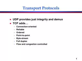
simple transport protocol “best effort” service, UDP segments may be: lost delivered out of order to application with no correction by UDP UDP will discard bad checksum segments if so configured by application connectionless: no handshaking between UDP sender, receiver each UDP segment handled independently of others Why is there a UDP? no connection establishment saves delay no congestion control: better delay & BW simple: small segment header UDP: User Datagram Protocol [RFC 768] • typical usage: realtime appl. • loss tolerant • rate sensitive • other uses (why?): • DNS • SNMP
UDP segment structure 32 bits Total length of segment (bytes) source port # dest port # length checksum application data (variable length) • Checksum computed over: • the whole segment • part of IP header: • both IP addresses • protocol field • total IP packet length • Checksum usage: • computed at destination to detect errors • in case of error, UDP will discard the segment, or
Sender: treat segment contents as sequence of 16-bit integers checksum: addition (1’s complement sum) of segment contents sender puts checksum value into UDP checksum field Receiver: compute checksum of received segment check if computed checksum equals checksum field value: NO - error detected YES - no error detected. UDP checksum Goal: detect “errors” (e.g., flipped bits) in transmitted segment
full duplex data: bi-directional data flow in same connection MSS: maximum segment size connection-oriented: handshaking (exchange of control msgs) init’s sender, receiver state before data exchange flow controlled: sender will not overwhelm receiver point-to-point: one sender, one receiver between sockets reliable, in-order byte steam: no “message boundaries” pipelined: TCP congestion and flow control set window size send & receive buffers TCP: OverviewRFCs: 793, 1122, 1323, 2018, 2581
32 bits source port # dest port # sequence number acknowledgement number head len not used rcvr window size U A P R S F checksum ptr urgent data Options (variable length) application data (variable length) TCP segment structure hdr length in 32 bit words URG: urgent data (generally not used) counting by bytes of data (not segments!) ACK: ACK # valid PSH: push data now (generally not used) # bytes rcvr willing to accept RST, SYN, FIN: connection estab (setup, teardown commands) Internet checksum (as in UDP)
SN: byte stream “number” of first byte in segment’s data AN: SN of next byte expected from other side cumulative ACK Qn: how receiver handles out-of-order segments? puts them in receive buffer but does not acknowledge them time TCP sequence # (SN) and ACK (AN) Host B Host A host A sends100 data bytes SN=42, AN=79, 100 data bytes host B ACKs 100 bytes and sends50 data bytes SN=79, AN=142, 50 data bytes host ACKs receipt of data , sends no dataWHY? SN=142, AN=129 , no data simple data transfer scenario (some time after conn. setup)
Connection Management: Objective Agree on initial sequence numbers a sender should not reuse a seq# before it is sure that all packets with the seq# are purged from the network the network guarantees that a packet too old will be purged from the network: network bounds the life time of each packet To avoid waiting for seq #s to disappear, start new session with a seq# far away from previous needs connection setup so that the sender tells the receiver initial seq# Agree on other initial parameters
Setup:establish connection between the hosts before exchanging data segments called: 3 way handshake initialize TCP variables: seq. #s buffers, flow control info (e.g. RcvWindow) client : connection initiator opens socket and cmds OS to connect it to server server : contacted by client has waiting socket accepts connection generates working socket Teardown:end of connection(we skip the details) Three way handshake: Step 1:client host sends TCP SYN segment to server specifies initial seq # no data Step 2:server host receives SYN, replies with SYNACK segment (also no data) allocates buffers specifies server initial SN & window size Step 3: client receives SYNACK, replies with ACK segment, which may contain data TCP Connection Management
B A SYN , SN = X SYNACK , SN = Y, AN = X+1 ACK , SN = X+1 , AN = Y+1 TCP Three-Way Handshake (TWH) X+1 Y+1 Send Buffer Send Buffer Y+1 X+1 Receive Buffer Receive Buffer
Connection Close Objective of closure handshake: each side can release resource and remove state about the connection Close the socket I am done. Are you done too? client server initial close : release resource? close release resource I am done too. Goodbye! close release resource