Download
1 / 90
900 likes | 1.14k Views
Explore concepts of Inter-VLAN routing and network switching in CCNP version 7. Learn about VLAN creation, router-on-a-stick configuration, and inter-VLAN communication. Understand ARP requests, default gateways, and routing between subnets. Discover how devices in different VLANs rely on routers for inter-VLAN communications. Review practical configurations for VLANs, trunking, and router interfaces. Enhance your knowledge of network segmentation and routing techniques in a multilayer network environment.

E N D
Inter-VLAN Routing CIS 187 Multilayer Switched Networks CCNP version 7 Rick Graziani Spring 2016
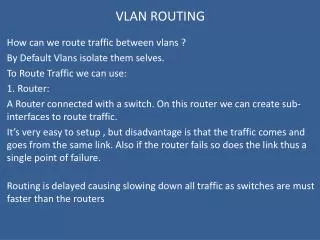
Internetwork Communications • Can two hosts on different subnets communicate without a router? • What would happen if a host tried to ping another host? • No they cannot communicate. • Would it send an ARP Request? Why or why not? • The host would not send an ARP Request because there is no default-gateway. C:>ping 172.16.30.100 Rick Graziani graziani@cabrillo.edu
Trunking with Default Gateway • What difference would it make if these hosts were on different VLANs? • The Broadcasts would not be forwarded out all ports by the switch. • Why does the host send the ARP Request to the router and not the destination host? After all they’re on the same switch. • The host doesn’t know where the destination host is, just that it’s not on its’ network. C:>ping 172.16.30.100 Rick Graziani graziani@cabrillo.edu
Internetwork Communications • Then Destination MAC Address is that of the same device as the Destination IP Address. • Check ARP cache for entry of Destination IP Address and its MAC Address. • If no entry, ARP Request Destination IP Address asking for MAC Address. • Then Destination MAC Address will be that of the Default Gateway. • Check ARP cache for entry of Default Gateway’s IP Address and its MAC Address. • If no entry, ARP Request Default Gateway’s IP Address asking for MAC Address. Rick Graziani graziani@cabrillo.edu
Legacy Inter-VLAN Routing 192.168.20.1 255.255.255.0 • Do not need VLANs for multiple subnets but…. • Router is required to connect (route) between subnets/VLANs 192.168.10.1 255.255.255.0 A B C D 192.168.10.10 255.255.255.0 GW 192.168.10.1 192.168.10.11 255.255.255.0 GW 192.168.10.1 192.168.20.12 255.255.255.0 GW 192.168.20.1 192.168.20.13 255.255.255.0 GW 192.168.20.1
Inter-VLAN Routing • VLAN is a logical group of ports, usually belonging to a single IP subnet to control the size of the broadcast domain. Rick Graziani graziani@cabrillo.edu
Inter-VLAN Routing • Even though devices in different VLANs may be “physically”connected, these devices cannot communicate without the services of a default gateway, a router. • This is known as Inter-VLAN Routing. Rick Graziani graziani@cabrillo.edu
Inter-VLAN Routing • The following devices are capable of providing inter-VLAN routing: • Any external router or group of routers with a separate interface in each VLAN • Any external router with an interface that supports trunking (router on a stick) • Any Layer 3 multilayer Catalyst switch Or trunk port Rick Graziani graziani@cabrillo.edu
Router with separate interfaces Not scalable S1(config)# vlan 10 S1(config-vlan)# exit S1(config)# vlan 30 S1(config-vlan)# exit S1(config)# interface f0/11 S1(config-if)# switchport access vlan 10 S1(config-if)# exit S1(config)# interface f0/4 S1(config-if)# switchport access vlan 10 S1(config-if)# exit S1(config)# interface f0/6 S1(config)# switchport access vlan 30 S1(config-if)# exit S1(config)# interface f0/5 S1(config-if)# switchport access vlan 30 R1(config)# interface g0/0 R1(config-if)# ip address 172.17.10.1 255.255.255.0 R1(config-if)# no shutdown R1(config)# exit R1(config-if)# interface g0/1 R1(config-if)# ip address 172.17.30.1 255.255.255.0 R1(config-if)# no shutdown
172.17.10.1 172.17.30.1 Router-on-a-Stick • The router-on-a-stick approach uses a different path to route between VLANs. • One of the router’s physical interfaces is configured as a 802.1Q trunk port so it can understand VLAN tags. • Logical subinterfaces are created; one subinterface per VLAN. • Each subinterface is configured with an IP address from the VLAN it represents. • VLAN members (hosts) are configured to use the subinterface address as a default gateway. • Only one of the router’s physical interface is used. VLAN 10 PC 2 172.17.10.30 VLAN 30 PC 4 172.17.30.55
S1(config)# vlan 10 S1(config-vlan)# vlan 30 S1(config-vlan)# exit S1(config)# interface f0/11 S1(config-if)# switchport mode access S1(config-if)# switchport access vlan 10 S1(config-if)# exit S1(config)# interface f0/6 S1(config-if)# switchport mode access S1(config-if)# switchport access vlan 30 S1(config-if)# exit S1(config-vlan)# interface f0/5 S1(config-if)# switchport mode trunk S1(config-if)# R1(config)# interface g0/0.10 R1(config-subif)# encapsulation dot1q 10 R1(config-subif)# ip address 172.17.10.1 255.255.255.0 R1(config-subif)# exit R1(config)# interface g0/0.30 R1(config-subif)# encapsulation dot1q 30 R1(config-subif)# ip address 172.17.30.1 255.255.255.0 R1(config-subif)# exit R1(config)# interface g0/0 R1(config-if)# no shutdown
R1# show vlans <output omitted> Virtual LAN ID: 10 (IEEE 802.1Q Encapsulation) vLAN Trunk Interface: GigabitEthernet0/0.10 Protocols Configured: Address: Received: Transmitted: IP 172.17.10.1 11 18 <output omitted> Virtual LAN ID: 30 (IEEE 802.1Q Encapsulation) vLAN Trunk Interface: GigabitEthernet0/0.30 Protocols Configured: Address: Received: Transmitted: IP 172.17.30.1 11 8 <output omitted>
R1# show ip route Codes: L - local, C - connected, S - static, R - RIP, M - mobile, B – BGP <output omitted> 172.17.0.0/16 is variably subnetted, 4 subnets, 2 masks C 172.17.10.0/24 is directly connected, GigabitEthernet0/0.10 L 172.17.10.1/32 is directly connected, GigabitEthernet0/0.10 C 172.17.30.0/24 is directly connected, GigabitEthernet0/0.30 L 172.17.30.1/32 is directly connected, GigabitEthernet0/0.30
External Routers: Advantages Disadvantages Advantages of external router usage: • Works with any switch because Layer 3 services are not required on the switch. • Many switches do not contain Layer 3 forwarding capability, especially switches that are used at the access layer of a hierarchical network. • Simple implementation. • Only one switch port and one router interface require configuration. • The router provides communication between VLANs. • The design and also the process for troubleshooting traffic flow become very simple because there is only one place in the network where VLANs interconnect.
External Routers: Advantages Disadvantages Disadvantages of external router usage: • The router is a single point of failure. • A single traffic path may become congested. • Latency may be introduced as frames leave and reenter the switch chassis multiple times and as the router makes software-based routing decisions. • Any time that traffic must flow between devices, latency is introduced. • In addition, routers make routing decisions in software, which always incur a greater latency penalty than switching with hardware. (??? Routers with line cards) • Physical limitations such as link congestions, latency and speed, it is not recommended to use it in large deployments.
Layer 3 Interfaces The Catalyst multilayer switches support three different types of Layer 3 interfaces: • Routed port— A pure Layer 3 interface similar to a routed port on a Cisco IOS router. • Switch virtual interface (SVI)— A virtual VLAN interface for inter-VLAN routing. In other words, SVIs are the virtual routed VLAN interfaces. • Bridge virtual interface (BVI)— A Layer 3 virtual bridging interface. (Not discussed) Rick Graziani graziani@cabrillo.edu
Routed Ports versus Switched Virtual Interfaces • Routed Ports – Just like a router, the port has an IP address/mask that makes it a member of that subnet. • SVI – The switch is a member of that IP subnet/VLAN. All switch ports that are a member of that VLAN can communicate with the switch
Multilayer Switch Interfaces • Performs both Layer 2 switching and interVLAN routing. • Layer 2 Interface: Access or Trunk ports • Layer 3 Interface: • Has an IP address assigned to it. • The Default Gateway for any hosts connected to that interface or VLAN. • Physical interface • Same as a router • Aka “Routed Port” • Example: interface gigabit 0/1 • Logical Interface • Represents an entire VLAN • Switched Virtual Interface (SVI) • Example: interface vlan 10 Layer 2: Access or Trunk Ports Physical Interface Logical Interface (SVI)
Multilayer Switch Interfaces • If in Layer 3 mode switchport interface command puts the port into Layer 2 mode. Is it a “switch” port? DLS1(config)# interface gig 0/2 DLS1(config-if)# noswitchport DLS1(config-if)# end DLS1# show interface gig 0/2 switchport Name: Gig0/2 Switchport: Disabled <output omitted> DLS1# config t DLS1(config)# interface gig 0/2 DLS1(config-if)# switchport DLS1(config-if)# end DLS1# show interface gig 0/2 switchport Name: Gig0/2 Switchport: Enabled <output omitted> Converts interface to Layer 3 Layer 3 Converts interface to Layer 2 Layer 2
SVI VLAN 10 192.168.10.1 255.255.255.0 SVI VLAN 20 192.168.20.1 255.255.255.0 A B C D 192.168.10.10 255.255.255.0 GW 192.168.10.1 192.168.10.11 255.255.255.0 GW 192.168.10.1 192.168.20.12 255.255.255.0 GW 192.168.20.1 192.168.20.13 255.255.255.0 GW 192.168.20.1 • Layer 3 functionality can also be enabled for an entire VLAN. • The IP address is assigned to the logical interface – the VLAN. • This is needed when routing is required between VLANs. • SVI (Switched Virtual Interface) • No physical connection • VLANs must be created before the SVI can be used. • The IP address associated of the VLAN interface is the default gateway of the workstation.
SVI VLAN 10 192.168.10.1 255.255.255.0 SVI VLAN 20 192.168.20.1 255.255.255.0 A B C D 192.168.10.10 255.255.255.0 GW 192.168.10.1 192.168.10.11 255.255.255.0 GW 192.168.10.1 192.168.20.12 255.255.255.0 GW 192.168.20.1 192.168.20.13 255.255.255.0 GW 192.168.20.1 <VLANs have been created or will be created when configured on the interface> S1(config)# interface range fastethernet 0/1 - 12 S1(config-if-range)# switchport mode access S1(config-if-range)# switchport access vlan10 S1(config-if-range)# exit S1(config)# interface range fastethernet 0/12 - 24 S1(config-if-range)# switchport mode access S1(config-if-range)# switchport access vlan20 S1(config-if-range)# end
SVI VLAN 10 192.168.10.1 255.255.255.0 SVI VLAN 20 192.168.20.1 255.255.255.0 A B C D 192.168.10.10 255.255.255.0 GW 192.168.10.1 192.168.10.11 255.255.255.0 GW 192.168.10.1 192.168.20.12 255.255.255.0 GW 192.168.20.1 192.168.20.13 255.255.255.0 GW 192.168.20.1 DLS1(config)# inter vlan 10 DLS1(config-if)# description Engineering VLAN DLS1(config-if)# ip address 192.168.10.1 255.255.255.0 DLS1(config-if)# no shutdown DLS1(config)# inter vlan 20 DLS1(config-if)# description IT VLAN DLS1(config-if)# ip address 192.168.20.1 255.255.255.0 DLS1(config-if)# no shutdown
SVI VLAN 10 192.168.10.1 255.255.255.0 SVI VLAN 20 192.168.20.1 255.255.255.0 A B C D 192.168.10.10 255.255.255.0 GW 192.168.10.1 192.168.10.11 255.255.255.0 GW 192.168.10.1 192.168.20.12 255.255.255.0 GW 192.168.20.1 192.168.20.13 255.255.255.0 GW 192.168.20.1 Alternative Configuration
SVI VLAN 10 192.168.10.1 255.255.255.0 SVI VLAN 20 192.168.20.1 255.255.255.0 Distribution Layer Switch Trunk Access Layer Switch A B C D 192.168.10.10 255.255.255.0 GW 192.168.10.1 192.168.10.11 255.255.255.0 GW 192.168.10.1 192.168.20.12 255.255.255.0 GW 192.168.20.1 192.168.20.13 255.255.255.0 GW 192.168.20.1 DLS1(config)# inter gig 0/2 DLS1(config-if)# switchport mode trunk ALS1(config)# inter fa 0/9 ALS1(config-if)# switchport mode trunk
Multilayer Switch Interfaces • Layer 2 or Layer 3 Interface? Is it a “switch” port? • Default on most Catalyst switches: Layer 2 • Default on Catalyst 6500: Layer 3 • Verify mode: • Switch# show interface type mod/num switchport • Switchport: Think Layer 2 • Enabled: Layer 2 • Disabled: Layer 3 Layer 2: Access or Trunk Ports Physical Interface (L3) Logical Interface (SVI – L3) DLS1# show interface gig 0/2 switchport Name: Gig0/2 Switchport: Enabled <output omitted>
Default Gateway (SVI) • Configure DLS1 to be the default gateway for VLANs 10 and 11. • All hosts on these VLANs will use these addresses as their default gateway addresses. DLS1(config)# inter vlan 99 DLS1(config-if)# description Management VLAN DLS1(config-if)# ip address 172.16.99.1 255.255.255.0 DLS1(config-if)# no shutdown DLS1(config)# inter vlan 10 DLS1(config-if)# description Engineering VLAN DLS1(config-if)# ip address 172.16.10.1 255.255.255.0 DLS1(config-if)# no shutdown DLS1(config)# inter vlan 11 DLS1(config-if)# description IT VLAN DLS1(config-if)# ip address 172.16.11.1 255.255.255.0 DLS1(config-if)# no shutdown
Default Gateway (SVI) • Configure DLS2 to be the default gateway for VLANs 20 and 21. • All hosts on these VLANs will use these addresses as their default gateway addresses. DLS2(config)# inter vlan 20 DLS2(config-if)# description Sales VLAN DLS2(config-if)# ip address 172.16.20.1 255.255.255.0 DLS2(config-if)# no shut DLS2(config)# inter vlan 21 DLS2(config-if)# description Administration VLAN DLS2(config-if)# ip address 172.16.21.1 255.255.255.0 DLS2(config-if)# no shut
Default Gateway (SVI) 172.16.10.10 255.255.255.0 Statically or Dynamically assigned 172.16.10.1
Routed Port– Physical Interfaces • Physical switch ports can operate as Layer 3 interfaces using the interface command: Switch(config)# interface type mod/num Switch(config-if)# noswitchport Switch(config-if)# ip address ip-address mask DLS1(config)# interface gig 0/1 DLS1(config-if)# no switchport DLS1(config-if)# ip address 192.168.1.1 255.255.255.252 DLS2(config)# interface gig 0/1 DLS2(config-if)# no switchport DLS2(config-if)# ip address 192.168.1.2 255.255.255.252
G0/0 10.10.10.1/24 G0/0 192.168.1.1/24 10.10.10.100/24 DF 10.10.10.1
interface vlan 10 172.16.10.1/24 interface vlan 11 172.16.11.1/24 interface vlan 20 172.16.20.1/24 interface vlan 21 172.16.21.1/24 Trunk =
Management VLAN (SVI) • For each device in the network we configured it to be a member of the management VLAN. On each switch Switch(config)#inter vlan 98 Switch(config-if)# description Management VLAN Switch(config-if)#ip address 172.16.98.x 255.255.255.0 Switch(config-if)# no shutdown Switch(config-if)# exit If you want to reach the management VLAN from other VLANs, assign this address to one of the multilayer switches (DLS1 and DLS2): ALS10(config)#ip default-gateway 172.16.98.1
Management VLAN (SVI) • For each device in the network we configured it to be a member of the management VLAN. On each switch Switch(config)#inter vlan 99 Switch(config-if)# description Management VLAN Switch(config-if)#ip address 172.16.99.x 255.255.255.0 Switch(config-if)# no shutdown Switch(config-if)# exit If you want to reach the management VLAN from other VLANs, assign this address to one of the multilayer switches (DLS1 and DLS2): ALS20(config)#ip default-gateway 172.16.99.1
interface vlan 98 172.16.98.1/24 On each switch DLS1(config)#inter vlan 98 DLS1(config-if)#ip address 172.16.98.1 255.255.255.0 DLS1(config-if)# no shutdown ALS10(config)#inter vlan 98 ALS10(config-if)#ip address 172.16.98.10 255.255.255.0 ALS10(config-if)# no shutdown ALS10(config)#ip default-gateway 172.16.98.1
interface vlan 98 172.16.98.1/24 interface vlan 99 172.16.99.1/24
SVI Autostate exclude • The SVI interface is brought up when one Layer 2 port in the VLAN has had time to converge (transition from STP listening-learning state to forwarding state). • The default action when a VLAN has multiple ports is that the SVI goes down when all ports in the VLAN go down. • This action prevents features such as routing protocols from using the VLAN interface as if it were fully operational and minimizes other problems, such as routing black holes. • You can use the SVI autostate exclude command to configure a port so that it is not included in the SVI line-state up-and-down calculation. • One example is the use of a network analyzer, where the traffic capture is being made without the device being an active participant in the VLAN that is assigned to the interface. • When the excluded port is in the up state, and all other ports in the VLAN are in the down state, the SVI state is changed to down. Switch(config)# interface fastethernet 0/1 Switch(config-if)# switchport autostate exclude
SVI: Advantages Disadvantages Advantages of SVI: • It is much faster than router-on-a-stick because everything is hardware switched and routed. • No need for external links from the switch to the router for routing. • Not limited to one link. Layer 2 EtherChannels can be used between the switches to get more bandwidth. • Latency is much lower because it does not need to leave the switch. Disadvantages of SVI: • It needs a Layer 3 switch to perform inter-VLAN routing, which is more expensive (for example, Catalyst 3500 series).
Routed Ports: Advantages Disadvantages Advantages of Routed Ports: • A multilayer switch can have SVI and routed ports in a single switch. How is this an advantage of a routed port? • Multilayer switches forward either Layer 2 or Layer 3 traffic in hardware, so it helps to do routing faster.
Switched Network Design • Core – Route/Switch packets quickly across between distribution multilayer switches. • Distribution – Route between VLANs/Subnets, ACLs • Access – Provide access to end devices and provide port security. L3 = Routed Ports, over IP, separate subnets L2 = SVI, VLANs over Trunks OR individual VLANs
Switched Network Design • As network technologies evolved, routing became faster and cheaper. • Today, routing can be performed at hardware speed. • One consequence of this evolution is that routing can be brought down to the core and the distribution layerswithout impacting network performance. • Because many users are in separate VLANs, and because each VLAN is usually a separate subnet, it is logical to configure the distribution switches as Layer 3 gateways for the users of each access switch VLAN. • This implies that each distribution switch must have IP addresses matching each access switch VLAN.
Verifying • Verify IP addresses DLS1#show ip inter brief Interface IP-Address OK? Method Status Protocol FastEthernet0/1 192.168.4.6 YES manual up up GigabitEthernet0/1 192.168.1.1 YES manual up up Vlan10 172.16.10.1 YES manual up up Vlan11 172.16.11.1 YES manual up up
InterVLAN Routing External Router No VLANs VLAN 1 External Router VLANs VLAN 2 VLAN 3 VLANs 1, 2, 3 Router on a stick VLANs or No VLANs Trunk VLAN 1 VLAN 2 Multilayer Switch VLAN 3 Trunk Multilayer Switch
Layer 3 EtherChannel • On Layer 3 switches, switched ports can be converted to routed ports. • These ports do not perform switching at Layer 2 anymore, but become Layer 3 ports that are similar to those that are found on router platforms. • EtherChannel links can also be created on Layer 3 links. Rick Graziani graziani@cabrillo.edu
DHCP • Similar to CCNA DHCP configuration. • See Lab! DSW1(config)# ip dhcp excluded-address 10.0.10.1 DSW1(config)# ip dhcp pool VLAN10POOL DSW1(config-dhcp)# network 10.0.10.0 255.255.255.0 DSW1(config-dhcp)# default-router 10.0.10.1 DSW1(config-dhcp)# lease 2 Rick Graziani graziani@cabrillo.edu
Multilayer Switching • Multilayer switching - ability of a Catalyst switch to support switching and routing of packets in hardware. • Optional support for Layers 4 through 7 switching in hardware as well. • Hardware switching: A route processor (Layer 3 engine) must download software-based routing, switching, access lists, QoS, and other information to the hardware for packet processing. CEF-Based MLS Traditional MLS Rick Graziani graziani@cabrillo.edu
Traditional and CEF-based MLS • Cisco Catalyst switches use either: • Traditional multilayer switching (traditional MLS) • A legacy feature • Cisco Express Forwarding (CEF)-based MLS architecture. • All leading-edge Catalyst switches support CEF-based multilayer switching CEF-Based MLS Traditional MLS Rick Graziani graziani@cabrillo.edu
Traditional MLS • Specialized application-specific integrated circuits (ASICs) perform Layer 2 rewrite operations of routed packets: • Source MAC address • Destination MAC address • Cyclic redundancy check (CRC). • Because the source and destination MAC addresses change during Layer 3 rewrites, the switch must recalculate the CRC for these new MAC addresses. Rick Graziani graziani@cabrillo.edu
Traditional MLS • Switch learns Layer 2 rewrite information from an MLS router via an MLS protocol. • netflow-based switching. • With traditional MLS, the Layer 3 engine (route processor) and switching ASICs work together to build Layer 3 entries on the switch. • Each entry can be populated in one of three ways: • Source IP address only • Source and destination IP addresses • Full Flow Information with Layer 4 protocol information. Rick Graziani graziani@cabrillo.edu