Download
1 / 17
290 likes | 559 Views
Inter-VLAN Routing. Review: VLANs. VLANs logically segment switched networks based on an organization's: Functions, Project teams, or Applications. Review: Broadcast Domains in VLANs. Broadcast domain is limited to a VLAN

E N D
Review: VLANs • VLANs logically segment switched networks based on an organization's: • Functions, • Project teams, or • Applications
Review: Broadcast Domains in VLANs • Broadcast domain is limited to a VLAN • Marketing, Sales and Engineering VLANs in the figure above have independent broadcast domains.
Review: Trunking VLANs • Trunk ports are created between switches to enable communication between hosts on a VLAN spread over different switches • VLAN ID is added to the basic Ethernet frame to identify to which VLAN it belongs • Two protocols are used for frames encapsulation • ISL - Cisco proprietary • 802.1Q – IEEE standard
VLANs and Trunking Figure above shows traffic from three VLANs carried over trunk ports between switches Traffic from each VLAN is identified by a VLAN ID (represented by a different colour)
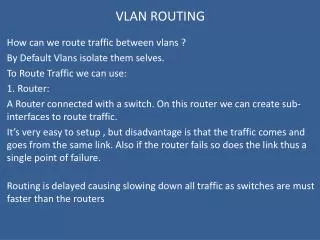
Inter- VLAN Communication • While Trunking enables communication between hosts on a VLAN spread over different switches, how do hosts connected to different VLANs communicate? • Traffic between different VLANs is routed • Router R is used to facilitate inter VLAN communication • For example, for PC1 to communicate to PC2, traffic is routed through the Router • How does PC2 communicates with PC5? • Hint: PC2 and PC5 are in the same subnet ROUTER
Inter-VLAN Issues and Solutions Two of the most common issues that arise in a multiple-VLAN environment are as follows: • The need for end-user devices to reach non-local hosts • The need for hosts on different VLANs to communicate
Inter –vlan communication • Two VLANs consisting of two servers and workstations of which one workstation has been placed along with the servers in VLAN 1, while the second workstation is placed in VLAN 2 • Both workstations require access to the File and Print servers, • Easy for workstation residing in VLAN 1 • Not for our workstation in VLAN 2. • we need to somehow route packets between the two VLANs • How can we achieve this?
VLAN Routing Solutions – Router with two Ethernet interfaces • A few years ago, this was one of the preferred and fastest methods to route packets between VLANs • Router with two Ethernet interfaces as shown in the diagram, connecting to both VLANs with an appropriate IP Address assigned to each interface. • Each host (servers and workstations) must either use the router's interface connected to their network as a 'default gateway’. • Expensive solution as it requires a dedicated router to router packets between our VLANs, • Limitation: Limited from an expandability prospective • In the case where there are more than two VLANs, additional Ethernet interfaces will be required,
VLAN Routing Solution No.2: Using A Router With One Ethernet (Trunk) Interface • The trunk link is required, using encapsulation the switches use (ISL or 802.1q), and enabling IP routing on the router side. • The router will need to be configured with two virtual interfaces, one for each VLAN, with the appropriate IP Address assigned to each one so routing can be performed.
VLAN Routing Solution No.3: Using A Server With Two Network Cards • One of the servers is configured to perform the routing between the two VLANs, reducing the overall cost as no dedicated equipment is required. • In order for the server to perform the routing, it requires two network cards - one for each VLAN • Appropriate IP Addresses assigned, therefore we have configured one with IP Addresses 192.168.1.1 and the other with 192.168.2.1. • Once this phase is complete, all we need to do is enable IP routing on the server.
VLAN Routing Solution No.4: InterVLAN Routing • Best VLAN routing solution out of all of the above. • InterVLAN routing makes use of the latest in technology switches ensuring a super fast, reliable, and acceptable cost routing solution. • The Cisco Catalyst 3550 series switches used here are layer 3 switches with built-in routing capabilities. • Configuring InterVLAN Routing with Catalyst 3750/3560/3550 Series Switches
VLAN Routing Solution No.2: Router on a Stick Router Fa0/0 One Physical router interface (Fa0/0 in the figure above) is required to facilitate inter-vlan communication. How does one physical router interface facilitates communication between VLANs?
Dividing Physical Interfaces into Logical Sub-interfaces • Physical Interface on a router are divided into sub-interfaces, one for each VLAN • Router supports one VLAN per sub-interface • Encapsulation is enabled on each sub-interface • Each sub-interface is given an IP address belonging to the sub-network address of a VLAN
Example: Router Physical and logical interfaces Enable physical interface Router_A(config)#interface fastethernet 0/0 Router_A(config-if)#no shutdown Router_A(config-if)#interface fastethernet 0/0.1 Router_A(config-subif)#encapsulation dot1q 1 Router_A(config-subif)#ip address 192.168.1.1 255.255.255.0 Router_A(config-if)#interface fastethernet 0/0.2 Router_A(config-subif)#encapsulation dot1q 10 Router_A(config-subif)#ip address 192.168.2.1 255.255.255.0 Router_A(config-if)#interface fastethernet 0/0.3 Router_A(config-subif)#encapsulation dot1q 20 Router_A(config-subif)#ip address 192.168.3.1 255.255.255.0 • Create logical interface 0/0.1 • Enable encapsulation with VLAN ID (1) • Assign IP address for VLAN 1 subnetwork
Summary • VLAN trunking allows many VLANs to be defined throughout an organization by adding special tags to frames to identify the VLAN to which they belong • When an end station in one VLAN needs to communicate with an end station in another VLAN, inter-VLAN communication is required. To support communication between VLANs routing is required.