Download
1 / 30
300 likes | 462 Views
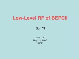
Low-Level RF for BEPC-2. Sun YI Huang Hong Lin Hai-ying IMAC’06 Apr. 27, 2006 IHEP. 2 LLRF stations are located respectively at the East/west RF hall beside each Klystron & PS, the test room is underground, the cryogenic hall is above the test SCC.

E N D
Low-Level RFfor BEPC-2 Sun YI Huang Hong Lin Hai-ying IMAC’06 Apr. 27, 2006 IHEP
2 LLRF stations are located respectively at the East/west RF hall beside each Klystron & PS, the test room is underground, the cryogenic hall is above the test SCC
The High power RF aging and the cold down of the #2—SCC will be taken at the test room on the next week
LLRF for the SRF west station50KW reached during the commissioning with Kly.
Interlock and tuner of 2#-SC passed the checking at the test room, RF aging can be start at RT
green=ok red=alarm white=no powerthe key parameters can be shown by a touch selection
Block diagram of the RT agingto avoid the outgas from the coupler to be absorbed and condensed by the Nb Surface at 4K
Hardware interlock for the #2--SCC • The RF interlock modules of the BEPC are reused for the Vacuum, LHe level, GHe pressure Arc, quench protection of a SCC, which switch off RF within 100us ( blue , 5CH/module) • Another kind interlock signals for the cooling water /wind and temp. are send to the Klystron ICS, which can be programmed by EPICS on the Web
The Q0 measurement and RF aging for SCC at 4KVc of SC can be modulated with a sharp pulse by LLRF
ALC & PLL loops for the Klystron are need to compress the noise of the 50KV pulse-modulating PS
Beam loading△f= -( Ib*Sinφs /2Vrf )* R/Q *frf • For KEK-B: • frf=508.885MHz , Vrf=1.2MV , U0=3.5MV , ∑Vrf=13MV • Ib=1.1A ,P+ =250KW φs=78.5 • △f≈-21 KH z • For BEPC-2: • frf=499.8MHz , Vrf=1.5MV , U0=0.121MV , Ib=0.9A , P+=123KW φs=85.4 • △f≈-14 KH z • The SCC cavity lengthing ~35um under a beam loading of 900mA / ring
Bandwidth difference between the KEKB and B-2 step motor move down 50um Beam injection to 1A piezo voltage 1600V to 600V with the beam decay
LLRF can Tune the freq. of 2#SC now, the step motor and HV piezo has been test. step motor Piezo lever HOM damper
Directional RF feedback loop (DRFB) reduce the impedence to be seen by the beam , μ=0 mode Robinson
μ=0 mode damping loop: hardware is under the designμ=-1 mode damping loop can be added inside LLRF in a day
There is a long way for LLRF to welcome the beam • INTL with the two ring vacuum for each SC • Interface with CCR ( remote control ) • beam signals / timing / RF phase drift between 2rings (IP shift) • RF phase 2bucket phase shift for the collision SW, Damping time ~20ms, switching speed control or not? • Beam trip diagnostic / fast Data acquisition for the detecting of the real reason of a trip, who first? e+ or e- , SRF or others result in the trip? which part troubled inside SRF? • Q0 online measurement ( every 2~3 month) • DRFB loop test / 0-mode damping loop • Two SC run protection mode • HOMs power and bunches/current margin PHOM=KlossqIb = Kloss (Ib2 / Nbf0) q=Ib/Nb*f0
HOM power should be limited within 10KW/SC, to prevent the HOM dampers from a outgasing and cracking,therefore we need establish a margin between the Ib and bunches
LLRF should be more complicated for the beam run than the test
Summary1) The challenge works of SRF are coming, specially for LLRF2) The RT aging of #2-SC ( Apr.30—May 2 )3) The cold down of #2-SC ( May 10—17 )4) Q0 measurement and pulse aging ( May 18—20 ) 5) #1—SC is under the final assembly now6) The cold down and High power test of #1—SC ( June ) 7) Installation of the two SC at tunnel ( July ) 8) SRF system commissioning ( Aug.—Sep.) Cryogenic + SCC + Kly.+ LLRF=?9) Beam commissioning with SRF ( Oct. ) The Beam may prove all • Thanks to Prof. K. Akai , T. Furuya, S. Mitsunobufor help. • Thanks to Dr. Wang Chaoen of TLS , for the useful suggestions. • Thanks to Prof. S. Kurokawa for the pushing on the co-operation. Thanks every expert