Download
1 / 16
160 likes | 164 Views
A. Gallo, M. Bellaveglia, L. Cacciotti. RF low level control & synchronization. SPARC review committee – ENEA Frascati – 16/11/2005. Summary. RF general layout and control system

E N D
A. Gallo, M. Bellaveglia, L. Cacciotti RF low level control&synchronization SPARC review committee – ENEA Frascati – 16/11/2005
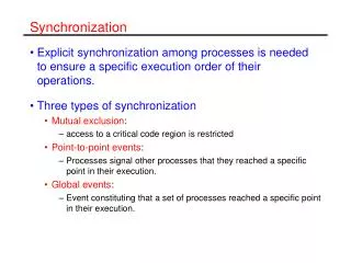
Summary • RF general layout and control system • Synchronization tests and results- demodulation channel resolution- oscillator characterization- time jitter measurements of laser system • Hardware installation in the SPARC area- RF distribution, demodulation and interlock boards- klystron driver amplifiers- cable connections- hardware calibration
RF control system • 25 signal to be monitored- waveform and phase monitor systems ready to use • 13 devices to be controlled- signal and power phase shifters- signal and power attenuators- each device is under control • To do- we are finishing to modify the main architecture to include phase feedback and devices control
Synchronization system SPARC phase stability specifications • SPARC phase I: ± 3° between the Laser pulse and the Linac RF (RF gun mainly) • SPARC phase II: ± 0.5° between the Laser pulse and the Linac RF (RF gun and RF compressor mainly) • Seeding@SPARC and/or next-generation experiments: ± 0.1° control of the bunch longitudinal position
Synchronization system Resolution of the Phase JitterMeasurement Equipment (CW) Measured Equivalent RMS Phase Noise 20 fs
Rhode&Schwarz SMT: @2.5GHz: - 130 fs (PLL BW=5kHz) - 65 fs (PLL BW=75kHz) @2.856GHz: - 183 fs (PLL BW=5kHz) - 92 fs (PLL BW=75kHz) HP8663A: @2.5GHz: - 85 fs (PLL BW=5kHz) - 72 fs (PLLBW=75kHz) Measured RMS Phase Noise Synchronization system Oscillator characterization
Synchronization system Laser time jitter measurements
Synchronization system Laser time jitter measurements Laser oscillator phase noise IR pulses, 79.33 MHz rep rate Measured phase noise 650 ÷ 750 fs rms Laser output phase noise UV pulses, 10 Hz rep rate Measured phase noise 630 fs ÷ 1 ps rms
Synchronization system Laser time jitter measurements • Preliminary phase noise measurements are marginally worse than system specifications (500 fs) and factory characterization of the laser oscillator (350 fs); • The measured phase noise values include contributions from the frequency down-conversion board, laser synchro-lock system and photodiodes; • The measured rms jitter is sensitive to the laser system set up (synchro-lock parameters) and power level; • More experimental activity is necessary to identify the major phase noise sources and try to reduce their contribution; • The measured phase noise levels are already inside the basic specification of SPARC.
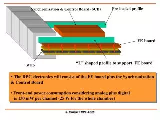
SPARC hall Installation • Main oscillator (2856MHz) • RF amplifier • Splitter • Demodulation board 1 • Demodulation board 2 • Distribution board • Fast interlock board • Industrial PC • DC voltage power supply
Installation • Modulator hall • 2 Milmega klystron drivers • Cable installation • 13 FSJ4-50B (for RF distribution and signal monitoring) • 2multipolar cables for interlock signals • 2 RG-223 cables for RF pulse timing signals Thanks to Alfredo Specacenere for setting up FSJ4 cables
RF distribution RF monitor RF timing Cabling Installation Timing & Laser RF low-level equipment
Installation Hardware calibration • demodulator channels - amplitude and phase offset - gain • diodes - gain • motorized phase shifters - encoder vs. phase shift - insertion loss • voltage controlled attenuators - voltage vs. attenuation - voltage vs. phase shift • RF switches - 1dB compression point • cables - attenuation - time delay
Installation Some typical calibration curves Motorized phase shifter Voltage controlled attenuator Demodulator channel
Conclusions • synchronization measurements meet specification for SPARC–phase 1 • control system is ready for first operations • hardware installation in SPARC area is completed RF low-level system is ready to begin tests on waveguides and RF gun