Download
1 / 20
210 likes | 313 Views
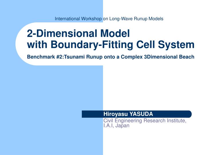
2-Dimensional Model with Boundary-Fitting Cell System Benchmark #2:Tsunami Runup onto a Complex 3Dimensional Beach. Hiroyasu YASUDA Civil Engineering Research Institute, I.A.I, Japan. Approach.

E N D
2-Dimensional Modelwith Boundary-Fitting Cell SystemBenchmark #2:Tsunami Runup onto a Complex 3Dimensional Beach Hiroyasu YASUDA Civil Engineering Research Institute, I.A.I, Japan
Approach • Major cause of extreme run-up height, 32m are occurred by the effect of topography rather than the 3D effect ? • When fine grids properly represent the topography in 2D model, we can obtain accurate calculation results ? In this study, focus on theRepresentation of Topography.
Concept of the BFC System • Cartesian coordinates, which are rectangle gird can’t freely represent characteristics of the topography using realistic grid size. • Triangle can freely represent all shape. • Boundary-Fitting Cell (B.F.C.) represent characteristics of the topography using Triangle cell. • BFC was developed for numerical analysis of flood-Inundation flows on complex urban area with Drainage network and Wall in (Yasuda et al, 2001). # 2D models with BFC was applied to Monai where is complex 3 Dimensional Beach.
BFC Area BFC Area
How to Create the BFC • Create procedure isvery importance. # Step1: Assign Ridge & Valley line. # Step2: Cell-side must accord with Contour as much as possible.
y x BFC for Monai pocket beach x=5.715, y=2.050 2.5cm z=5.0cm z=7.5cm z=10.0cm x=4.950,y=1.825
BFC of Monai pocket beach • Number of Cells: 670 • Area of Cell: • Average 0.625 cm2 • Range 0.125~2.185 cm2 • Side-length of Cell: • Average 1.25 cm • Range 0.5~3.25 cm • Cell size is approximately half of 1.4 cm rectangle gird.
Equations & I.C., B.C. • Eq.: Expanded Linear Long wave theory for BFC. • B.C.: Temporal water-level variations on boundary cells. • I.C.: D = 0.0 at the whole area • M.B.C.: Tohoku Univ. model • dt = 0.00125(s) • Manning's n = 0.025 • Numerical Scheme : Explicit FDM, Leap-Flog
Definition of Calculation Point • Eq.: Expanded Linear Long wave theory. Continuity Equation Momentum Equation
Cell for Boundary • On boundary cells,Temporal water-level variations, which were calculated by shallow water theory are given.
BFC & Rectangle Grid area • B.C. & I.C. Reflective BFC Area 2D Shallow Water Area Reflective
Equations & I.C., B.C. • Eq.:2-D nonlinear long wave theory • B.C. • North & South wall : Reflective • East wall : Runup & Reflective • West wall : Incident wave • I.C.: x,y direction Flux = 0.
C.C. & Numerical Scheme • dx = dy =0.014 (m) • dt = 0.00125 (s) • Manning's n = 0.025 at the whole area • Numerical Scheme • Local and Pressure term : Leap-Frog (2nd order) • Convection term : Up-wind (1st order) • Friction term : semi implicit C.F.L = 0.12
Visualizing Area BFC Area Visualizing Area (2D Shallow water)
Water Level (cm) -2.25 -1.5 -0.75 0.00 0.75 1.50 2.25 z=7.50cm z=2.50cm y z=0.00cm x Calculation Results - Monai area x=5.488, y=2.902 t =17.70 sec, Maximum runup at Monai. Maximum height: 7.10cm BFC Area x=3.000y=1.000
Calculation Results - Temporal water-surface variations Ch.5 (x = 4.521, y = 1.196) Ch.7 (x = 4.521, y = 1.696) Ch.9 (x = 4.521, y = 2.196)
Depth of Water (cm) 0.0 0.5 1.0 1.5 2.0 2.5 3.0 Calculation Results of BFC area • Maximum Inundation areaat 17.90 (s).
Depth of Water (cm) 0.0 0.5 1.0 1.5 2.0 2.5 3.0 Calculation Results of BFC area by 2D Shallow water Eq. • Maximum Inundation areaat 17.70 (s).
Conclusions • If we can use the fine grid as about 5 m,2D model with Tohoku Univ. M.B.C is sufficient in order to reproduce the runup-height on complex 3D beach. • The BFC system can freely represent the topography, and has various possibilities !
Animation gallery • If you want to watch the animation files, Please visit web site of our lab. URL: http://river.ceri.go.jp/data/yasu/catalina/index.html