Download
1 / 37
370 likes | 531 Views
September 2008. Level 1, V2.0. Training Manual: KI7600 Series Power Meters. Course Contents. General Features Models Detector Types Instrument Care Prepare instrument. Modes of operation Display Modes Built in visible laser (KI7601) Memory Operation. 1./ General Features.

E N D
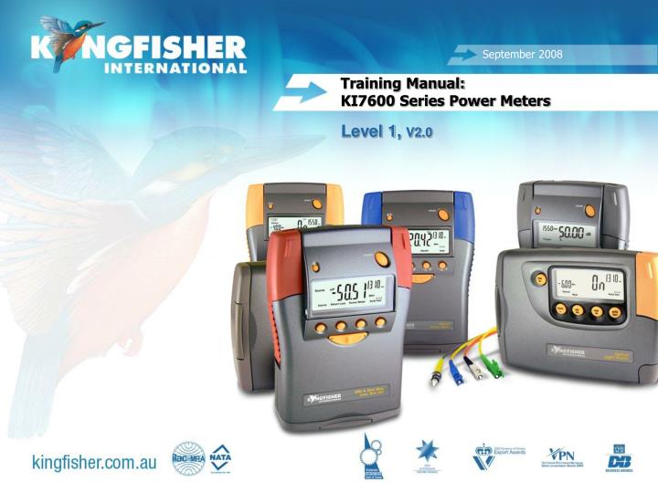
September 2008 Level 1, V2.0 Training Manual: KI7600 Series Power Meters 20080825
Course Contents • General Features • Models • Detector Types • Instrument Care • Prepare instrument • Modes of operation • Display Modes • Built in visible laser (KI7601) • Memory Operation
1./ General Features • Low skill operation • Autotest capability • Autotest compatible with Agilent N series instruments • Calibrated at multiple wavelengths • 1% factory calibration accuracy • Supplied with calibration certificate • Industry standard connectors –Including SFF • High contrast LCD display with backlight • Battery life – 190-360 hours • DC power socket • Memory • USB Computer interface • Test tone detection • Built in VLS variant (KI7601) • 3 year re-calibration interval • 3 year warranty 3
2./ Models • There are two model styles: • KI7600: the most popular. • KI7601: fitted with a Visible source on left hand port • There are two Computer interface styles: • Early instruments: RS232 port • Current instruments: USB Type A port • RS232 & USB models have minor operational differences
3./ Detector Types • Choose detector to suit your application. • InGaAs: Telco & LAN • Enhanced InGaAs with good response @ 850 nm • Power Levels of up to +5 dBm • Most accurate detector type at Telco wavelengths • H series: High power – CATV, DWDM • Enhanced H3 with good response @ 850 nm • Power level configurations of up to +27 dBm • Filtered InGaAs Other detector types available for specific wavelength and power requirements.
4./ Instrument Care • Keep the instrument in its carry case during storage and transport • Use only high quality 1.2-1.5 volt batteries. (Do not use lithium batteries) • For prolonged storage remove batteries. • The instrument is resistant to normal dust and moisture, however it is not waterproof. • If moisture gets into the instrument, remove batteries & dry it carefully before reuse • Where possible, keep instrument away from strong sunlight. • Clean the instrument case using Iso-Propyl-Alcohol (IPA) or other non solvent cleaning agents. • Ensure instrument input power rating is not exceeded DO NOT use Acetone or other active solvents as damage may result.
5./ Prepare Instrument • Hand carry strap • Control buttons • Power supply – batteries & external • Turn On / Off • Fit / Remove adaptors • Test cord selection
a./ Hand carry strap • If required, fit provided hand carry strap: • Provides enhanced on-the-job instrument care
b./ Control buttons Hidden Keypad Computer Port DC Power Turn On/Off RS232: Back Light USB: Memory store Detector Optional VLS Function buttons λ toggle Battery compartment
c./ Power supply - batteries • To Install Batteries. • Hold instrument in both hands with battery compartment uppermost and with thumbs resting on battery compartment latch. • Press latch down and push away from case. • Insert batteries. • Insert ‘AA’ cells using the supplied AA-C battery converters. • Battery life. • Alkaline ‘C’ batteries : 360 hours meter, 190 hrs VFL • Alkaline ‘AA’ batteries : approx 75 hours meter • Low Battery Display. • Indicator shows when approximately 10 hours left.
Power Supply - external • All Instruments: • External power supply disconnects the batteries • Rechargeable batteries must be removed for charging • RS232: • Via the DC power socket • USB: • Via the DC socket or via the USB cord • Plug Pack Requirements: • 2.5 mm DC power plug • 6-12 V DC @ 300 mA maximum • +Ve pin DC USB
d./ Turn On / Off 10 minutes auto Off or Permanent operation Push the oval [POWER] button to turn ON or OFF Low battery indicator To defeat auto time out.Hold down [POWER] for 3 seconds during turn ON
e./ Adaptor - fitting • Industry standard SC adaptors • We recommend ceramic/zirconia sleeves Slot to outside
Adaptor - removal • Current models: • Locate quick release button on rear of instrument at base of connector housing • Push and hold button in • Pull out existing adaptor • Fit new adaptor • OR • Remove as per ‘early models’ • Early models: • Move adaptor interface to mid position • Pull out existing adaptor • Fit new adaptor
f./ Test cord selection • Power meters accept PC and APC connectors. • KI7601 has built in visible laser source (VLS) • Must specify visible source to be PC or APC when ordering • Instrument ports are colour coded: • VLS connector: • PC housing: BLUE • APC housing: GREEN Specify PC or APC VLS 16
6./ Modes of Operation • 4 main modes of operation • Autotest: • automatically toggles between all λs • Preferred mode for loss testing as testing time is greatly reduced. • Minimises error as meter always displays correct λ. • Manual: • Single λ operation • Preferred mode for level monitoring. • Modulated: • Displays incoming modulation frequency • KITS software: • Under software control
a./ Autotest • When receiving light from a compliant source operating in Autotest mode, the meter will auto toggle between λs • Power meter receives data which contains wavelength, source serial number and nominal source output power. • If power meter not calibrated at an incoming wavelength it will ignore it but remain in sync with other wavelengths. • If incoming power level too low at a particular wavelength it will ignore it but remain in sync with other wavelengths. Simplest mode for loss testing 18
b./ Manual Mode • If not in power meter mode • Press [Power Meter] • To select wavelength • Toggle [-/+]. • Note: • Wavelength toggle is not circular • Most meters have the common wavelengths grouped together for speed of access when used in manual mode. E.g. 850, 1300, 1310, 1550, 1625 nm are together [Power Meter] [-/+]
c./ Test Tone • When receiving test tone or low level modulation • Power meter displays modulated frequency and beeps • Built in feature cannot be disabled
Direct Interface to - KITS™ Testing & Reporting softwareInstrument under computer control • d./ KITS™ • Familiar Excel™ User Interface • Inbuilt multi language support • Memory extract to Excel spreadsheet or CSV file • One Click Real Time Data Capture • Standards based & user definable analysis • Data Logging • User Customisable reports • Fee for service user customisation service 21
7./ Display Modes • Absolute dBm / Relative dBr mode • Setting the Reference • Log dBm / Linear W mode
a./ Absolute / Relative Mode • Absolute Mode: • Measure actual power level at a particular location – dBm • Relative Mode: • Measure power level ‘relative’ to a particular location - dBr -6.99 dBm -47.71 dBm 0 dBr -40.72 dBr
LCD Display • Main display features - Absolute Mode: • Calibrated wavelength – nm • Received power - dBm • Nominal ‘Autotest’ source power dBm • Only if Autotest source • Main display features - Relative Mode: • Calibrated wavelength - nm • Relative received power - dBr • Reference power - dBm λ Received Power Nominal Source Power λ Reference Power Relative Power
Toggle Absolute / Relative Mode • If not in power meter mode: • Press [Power Meter] (1) • To enter Relative mode (dBr) • Press [Abs/Rel] (2) • To return to Absolute mode (dBm): • Press [Abs/Rel] (3) 1 2 3 25
b./ Setting the Reference • Must be in Relative mode dBr not Absolute mode dBm • Press and hold soft button [Set Ref] for 3 seconds • Meter will beep 5 times • Autotest mode: meter will display ‘busy’ & zero at all incoming wavelengths • Manual mode: zero at indicated wavelength • Meter will not zero if display is ‘Lo’ • Referencing is retained at power off. [Set Ref]
c./ Log / Linear Mode 1 • To enable: • Open hidden keypad • RS232: press [dBm/w] (1) • USB: press [dB/W] (2) • To return to dB mode: • Repeat above key press • Must be in manual mode to switch between log & linear modes. • Linear display functions in both Manual & Autotest • Resets to log (dBm) mode at power off 2
8./ KI7601 - Visible Laser • To turn On: • Press [Source](1) • To toggle flashing: • Press [Mod] (2) • To turn Off: • Toggle [-/+](3) 2 1 3 28
9./ Memory Operation Memory clear Memory store Memory store at a location Memory recall Memory extract to computer 29
a./ Memory clear • Instrument must be in Manual mode, not Autotest • Open hidden keypad: • RS232: • Press [CANCEL] and [RECALL MEMORY] simultaneously and hold for a few seconds. • USB: • Press [MR] and [EXIT] simultaneously and hold for a few seconds. RS2 3 2 U S B • Meter will beep 5 times • ‘clr’ will display when memory cleared.
a./ Memory - Store • RS232: • Open hidden keypad • Press [STORE] • USB: • Press [M+] • During Store operation • Display will blank or display BUSY • Meter will beep once • Memory location displayed top right side • A full memory is indicated by a repeating buzzer • In Autotest stores:- • All λs transmitted, Absolute Power, Reference value and S/N of the remote unit [STORE] M+
c./ Memory – RS232 Store at a location 1 • Exit Autotest Mode: • Open hidden keypad • Press [RECALL MEMORY] (1) • Toggle [-/+] to desired memory location (2) • Press [SET] (3) • When ready - Press [STORE](4) • Note: memory writes continue from this location. • Typical use: • Match memory location to fibre number 3 4 2
c./ Memory - USB Store at a location 3 1 • Exit Autotest Mode: • Open hidden keypad • Press [MR] (1) • Toggle [-/+] to desired memory location (2) • Press [Set](3) • When ready - Press [M+](4) • Note: memory writes continue from this location. • Typical use: • Match memory location to fibre number 4 2
d./ Memory – Recall – RS232 1 4 • Exit Autotest Mode • Open hidden keypad • RS232: • Push [RECALL MEMORY](1) • Toggle [-/+] to desired memory location (2) • Display alternates between λ and memory number • Push [ABS/REL] to alternate between dBr & dBm (3) • dBr: Reference shown on LHS of LCD. • Hint: Push & hold [ABS/REL] to display reference in display centre. • Press [-/+] to scroll λ and memory (2) • Exit memory display by pressing [CANCEL](4) 3 2
d./ Memory – Recall – USB 4 1 • Exit Autotest Mode • Open hidden keypad • USB: • Push [MR](1) • Toggle [-/+] to desired memory location (2) • Display alternates between λ and memory number • Push [ABS/REL] to alternate between dBr & dBm (3) • dBr: Reference shown on LHS of LCD. • Hint: Push & hold [ABS/REL] to display reference in display centre. • Press [-/+] to scroll λ and memory (2) • Exit memory display by pressing [Exit] (4) 3 2
e./ Memory Extract to Computer Memory retrieve to computer is covered in the KITS™ training PPT Download to KITS software or to CSF file KITS: Familiar Excel™ user interface CSV File: For those who do not use Microsoft Office
Application NotesComprehensive selection available atwww.kingfisher.com.au/ApplicationNotes.htm