Download
1 / 27
320 likes | 793 Views
Plans. How do the computed BJT I-Vs compare with expts? Can we understand the discrepancies? What does the gain look like? AC properties (small signal and transient response). Common Base. Common Emitter. BJT – Real Characteristics. What’s wrong with these pictures? Common Base:

E N D
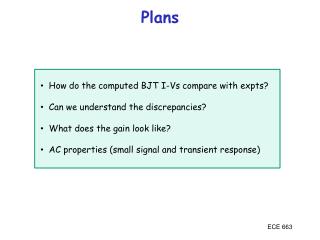
Plans • How do the computed BJT I-Vs compare with expts? • Can we understand the discrepancies? • What does the gain look like? • AC properties (small signal and transient response) ECE 663
Common Base ECE 663
Common Emitter ECE 663
BJT – Real Characteristics • What’s wrong with these pictures? • Common Base: • Input characteristic shows VCB dependence • Output shows breakdown at VCB0 • Common Emitter • Input characteristic pretty good agreement • Output characteristic: • Upward slope in IC – quasilinear VEC dependence • Breakdown at VCE0 • Upturn prior to breakdown ECE 663
Base Width Modulation: “Early” Effect • Base width has been assumed to be constant • When bias voltages change, depletion widths change and the effective base width will be a function of the bias voltages • Most of the effect comes from the C-B junction since the bias on the collector is usually larger than that on the E-B junction Base width gets smaller as applied voltages get larger ECE 663
Early Effect: Common Base Input Characteristic Ebers-Moll • Exponential prefactor will increase as VCB increases (W decreases) Assuming –VCB > few kT/q and W/LB << 1 ECE 663
Early Effect: Common Emitter Output Characteristic • If NC << NB most of the depletion is in the collector and modulation of base width is minimized – reduced Early Effect ECE 663
Early Voltage J M Early ECE 663
Avalanche Multiplication Breakdown • Common Base: Similar to single p-n junction VCB0 VBD(B-C) • Common Emitter: more complicated • holes injected by FB emitter to base • holes generate e-p pairs in C-B depletion • e- drift back into base • e- injected to emitter • more holes into base….. ECE 663
Avalanche Breakdown: Common Emitter • IC when M1/dc • M only needs to be slightly greater than unity • VCEO<VCB0 – Breakdown voltage is lower for common Emitter mode than common Base mode or p-n breakdown voltage due to amplification effect within the transistor ECE 663
Ideal W/base width mod Early Effect W/base width mod & avalanche multiplication ECE 663
Graded Base • Implant or diffusion leads to doping profile • Doping profile leads to E field • If Emitter is on top layer – E field acts to push carriers toward the collector • Improved speed if limited by base transport time ECE 663
Si-Ge HBT’s for BiCMOS • Dilemma for bipolar transistors: • For high frequency operation want low base resistance – high base doping • For high current gain want to minimize hole injection into emitter (npn) – low base doping • Solution HBT – heterojunction bipolar transistors • For CMOS integration use Si1-x Gex system • Bandgap difference (1.12 eV Si, 1.0 eV, Si0.8Ge0.2) • 80% EG in VB • 0.1 eV additional barrier for holes to emitter • Higher base doping w/same gain • Selective growth of pseudomorphic Ge on Si substrate ECE 663
Si-Ge HBT’s for BiCMOS ECE 663
Bandgaps and alignments ECE 663
Si-Ge Heterostructure • Most of the bandgap difference shows up in the valence band ECE 663
Band Diagram for SiGe HBT ECE 663
Si-Ge HBT’s ECE 663
Si-Ge HBT’s bdc = DBLENE /DEWNB bdc = DBLE(ni2/NB)/DEW(ni2/NE) bHBTdc = bdc(nSii)2/(nGei) 2 = bdc e(EGeG-ESiG)/2kT ECE 663
Gain Plots ECE 663
Gummel Plot Hermann-Gummel ECE 663
BJT Small Signal Response • Assume the transistor can follow AC voltages and currents quasistatically (frequency not too high). Also neglect capacitances of pn junctions and other parasitics Common Emitter equivalent circuit model ECE 663
BJT Small Signal Response ECE 663
BJT Transient Behavior ECE 663