Download
1 / 28
530 likes | 1.33k Views
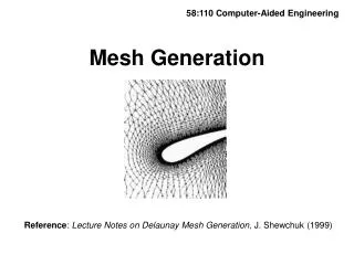
58:110 Computer-Aided Engineering. Mesh Generation. Reference : Lecture Notes on Delaunay Mesh Generation , J. Shewchuk (1999). Desirable Mesh Properties. Compatible with solver Finite-difference solver requires mesh to follow lines of constant coordinate

E N D
58:110 Computer-Aided Engineering Mesh Generation Reference: Lecture Notes on Delaunay Mesh Generation, J. Shewchuk (1999)
Desirable Mesh Properties • Compatible with solver • Finite-difference solver requires mesh to follow lines of constant coordinate • Most finite-element and finite-volume codes are written only for grid elements of certain shapes (e.g., tetrahedron, hexahedral, etc.)
2. Nodes of adjacent mesh elements are the same Examples of meshes that are not allowed
3. Element angles close to 90 degrees • Meshes with angles that are too small or too large lead to inaccurate solutions, ill-conditioned matrices, and slow (or no) convergence of iterative solvers Poor Mesh Good Mesh
4. Provides adequate resolution of computed fields • Meshes must be finer in fluid/thermal boundary layers, near cracks in solids, near joints, within vortex cores, etc. U
5. Uses minimum number of elements • Triangles use twice as many elements as quadralaturals • Tetrehedrals use six times as many elements as hexahedrals 3 1 1 2 2
6. Easily refinable • We often want to do tests of resolution by varying the grid size in some systematic manner • Useful property for multigrid matrix iteration solvers and multiscale computational approaches
7. Easy to generate • Triangles and tetrahedrons are easy to generate using automatic grid generators • Depends on capabilities of grid generators
Types of Meshes A. Structured • A set of indices (i,j,k) exist, with the number of indices equal to the space dimension, such that each element has a unique index set in which the indices of adjacent elements differ by at most unity in each index
Example Structured Mesh (1,5) (1,4) (1,3) (1,2) (3,1) (2,1) (1,1) (4,1) (5,1)
A.1. Body-Fitted • Structured mesh in which lines connecting nodes lie on constant coordinate surfaces of some coordinate system • Required for finite-difference solver Flow past a sphere – done using a spherical coordinate body-fitted grid
A.2. Multi-Block • Mesh formed by joining together several structured meshes Vortex-Blade Interaction
A.3 Chimera Mesh • Chimera meshes are formed from two structured meshes that overlap. They are used to provide enhanced local resolution with structured meshes. The user must continually interpolate from one mesh to the other during the problem solution.
B. Unstructured • Mesh formed by connecting lines between nodes, such that no nodes are contained within elements • Unstructured meshes provide greater freedom in providing fine resolution to one region, but having course resolution in other areas • Unstructured meshes significantly reduce the number of nodal points • Some solvers do not function as well with unstructured meshes as they do with structured or block-structured meshes
Structured and Unstructured Meshes Mesh for earthquake prediction in Los Angeles Basin: Structured mesh has five times as many nodes, but yields same accuracy in numerical simulation as the unstructured mesh
Delaunay Triangularization • Method for automatic generation of an “optimal” unstructured mesh given a set of N points • Property: Delaunay triangularization maximizes the minimum angle among all possible triangularizations of a set of points Example of Delaunay triangularization
Given: Set of N points, denoted by V Triangularization (T): A trangularization of V is a set of triangles T • whose vertices coincide with V • whose interiors do not overlap each other • who contain no points of V within the interior of any triangle There exist many different triangularizations of a given set of points.
Geometrical Concepts Circumcircle: A circle passing through two points u and v Any two points have an infinite number of circumcircles
Delaunay Triangularization (D) Definition: A Delaunay triangularization is a set of triangles T in which each edge of T possesses at least one empty circumcircle. Empty: A circumcircle is said to be empty if it contains no nodes of the set V Not Empty Empty Not Empty
Delaunay Triangles Circumcircle of a triangle = circle passing through all three vertices of the triangle
Delaunay Triangles Definition: A triangle is Delaunay with respect to a set of points V if its circumcircle is empty Theorem: A triangle is Delauney iff each of its edges are Delaunay If a triangle is not Delaunay, then one of its edges (in this case edge e) is not Delaunay.
Min-Containment Circle Definition: The min-containment circle is the smallest circle that contains all vertices of a triangle.
Existence and Uniqueness of Delaunay Triangularization • It isunique(i.e.,only one triangularization is Delaunay for a given set of points V) • It is guaranteed toexist provided that there are no four points that all lie on a circle
Extremum Properties of Delaunay Triangularization Among all triangularizations T, the Delaunay triangularization: • maximizes the minimum angle in T • minimizes the largest circumcircle in T • minimizes the largest min-containment circle in T
Algorithm for Forming a Delaunay Triangularization 1. Start with two points along the side to make an edge 2. Search surrounding points to see if they form a Delaunay triangle with the edge 3. Go to one of the new edges of this triangle and repeat Note: The calculation can be significantly speeded up by using a background Cartesian grid to help identify nearby points
Advancing Fronts When meshing the exterior of an object, start with edges on the object and search outward to find triangles. Several stages in the progression of an advancing front algorithm
Delaunay Tetrehedralization The 3D version of Delaunay triangularization