Download
1 / 25
260 likes | 385 Views
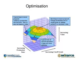
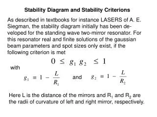
3 . 7. Stability and Optimisation. Improving engine stability and performance. Improving Stability. Optimizing the engine to improve stability. Stability. Stability problems can emerge within physics engines (and other forms of computational simulation) due to the following problems:

E N D
3.7.Stability and Optimisation Improving engine stability and performance
Improving Stability Optimizing the engine to improve stability
Stability Stability problems can emerge within physics engines (and other forms of computational simulation) due to the following problems: Unforeseen interactions among different software components (which individually behave reasonably). Inaccuracies in the equations used to model the physical behaviour or adverse effects of modelling assumptions Inherent inaccuracy due to floating point arithmetic performed by the computer Some measures that can improve stability include:
Quaternion Drift Each frame a rigid body transform matrix is built using the body’s position vector and orientation quaternion. Following resolution a body’s position and orientation may be updated. Over time, the repeated application of the above will result in an accumulated error due to floating point inaccuracies (where, for example, the orientation quaternion may become un-normalised, and hence stop representing a rotation). By periodically re-normalising the quaternion it becomes possible to limit the effect of drift due to numerical inaccuracies.
Improving Mathematical Accuracy As floating point numbers are represented using a series of significant digits (the “mantissa” and an exponent), manipulating two numbers with significantly different exponents will result in significant numerical inaccuracy. This can be a problem if: An object’s position is very distance from the origin and its position is updated by a small amount. The physics simulation includes bodies with masses/velocities/etc. that differ by several orders of magnitude. Whilst unavoidable, effects can be limited by using numbers with greater accuracy (i.e. doubles) – although this will also increase memory usage and require more processing time (platform dependent).
Other Stability Improvements See the recommended course text for details on how to improve stability due to: Removing slippage due to interpenetration on slopes Integration stability using second-order Netwon-Euler or fourth-order Runga–Kutta Using pessimistic collision detection
Improving Performance Optimizing the engine to improve performance
To optimize or not to optimize Whilst the general advice for any form of optimisation is ‘don’t unless you need to’, the computationally intensive nature of a real-time physics simulation entails that there is likely a need to optimise code in order to handle a large number of interacting objects. The following slides explore a number of design-related optimisations, extending the current functionality and offering improved performance. • Aside: As with most forms of code optimisation, a profiler is vital in terms of analysisingrun-time costs.
Sleep Consider a stable stack of boxes. It involves multiple points of contacts and numerous resolve iterations to reach a conclusion of ‘no movement’. This is wasted computational effort in terms of visual impact and can be avoided by not simulating objects that are stable and not moving. In a typical game, most objects will end up in a stable state (unless subject to a consistent input force). Skipping the simulation of objects at rest is called putting them to “sleep” and will typically provide a considerable boost in performance in most situations. A means of “waking” up sleeping objects will also be needed.
Sleep An object which is asleep can be effectively removed from the physics simulation. Contacts should still be generated between objects which are asleep as they will be of use whenever an object receives a knock from an awake body (although if contacts are cached, contact generation between two sleeping objects can be omitted). As a sleeping body will have no velocity or rotation, contacts between two sleeping bodies can be omitted from the velocity and position resolution algorithms.
Sleep Variables The following variables can be used to introduce a sleep system: isAwake: boolean flag indicating if the body is currently awake. canSleep: boolean flag indicating if the body can be put to sleep (some objects. e.g. those under user control, should probably never be put to sleep) motion: numerical measurement of the object’s current movement (linear/angular). If it falls under a threshold then the object can be put to sleep. If an object is awakened, then the motion should be given a minimum initial value above the threshold to prevent the object from falling back to sleep.
Putting Objects to Sleep At each frame the object’s motion parameter is updated. Should it fall under a threshold (arising from a period of zero or near-zero velocity) it is put to sleep. If the threshold is too low, then objects may never go to sleep (or take a very long time to go to sleep). If too high, then visually moving bodies may suddenly fall asleep. The motion value encapsulates the linear/angular velocity of the object by ‘measuring’ the total kinetic energy of the object. This is given by (where im is the moment of inertia about the current axis of rotation of the body) In order to avoid the problem of two objects of different masses or moments of inertia, but similar linear/angular velocities, from falling asleep at different times, the above form is simplified as follows:
Putting Objects to Sleep In order to provide a recent history of motion (preventing a body which has a sudden halting collision from immediately falling asleep) a recency-weighted average of the motion is maintained: The bias parameter controls how much significance is given to previous values. The bias should take into account the duration of the frame (longer frames should apply a stronger bias), this can be accomplished by: It is also useful to provide a cap on the maximum permitted motion value (e.g. if (motion > 10*sleepEpsilon) motion = 10*sleepEpsilon;) as this ensures that very large motion values are not generated (which can take a long time to drop down once the object has stopped). motion = bias*motion + (1-bias)*currentMotion; float bias = Math.Pow(baseBias, duration);
Waking Objects Up Objects, if asleep, need to be awakened when they are subject to a collision with a non-sleeping object. This can be done during the resolve process when considering contacts, i.e. whenever a contact has been selected to be resolved (because it has the largest closing velocity or interpenetration) if one of the bodies associated with the contact is asleep then it can be awakened.
Waking Objects Up This approach extends to include a series of collisions, whereby the resolve process will awaken sleeping objects which interpenetrate or have a suitable significant closing velocity.
Waking Objects Up An object should also be put into the awake state whenever it is subject to an applied force or torque (e.g. arising from some force/torque generator). Forces which are always present (and potentially applied using some other mechanism other than a force generator – e.g. directly applied within object integration) might be excluded. Aside: When a level is loaded all objects will likely be placed into a resting position (by the designer), entailing that all objects can be set to asleep by default. Hence, objects will require physical simulation only once they have been subject to a collision and will hopefully quickly return to a sleeping state.
Margins of Error for Penetration and Velocity Velocity or position change during collision resolution tends to be non-linear, with initial iterations accounting for most change and later iterations accounting for increasingly smaller amounts of change. As such, there is a danger many of the later iterations will not result in any perceptible change.
Margins of Error for Penetration and Velocity This problem can be largely avoided by introducing a small tolerance limit to the velocity and interpenetration resolution, i.e. a small closing velocity or small interpenetration depth will not be subject to resolve iterations. It can be simply implemented for penetration (with a similar solution for velocity) as: for( inti = 0; i < positionIterations; i++) { Contact worstContact = NULL; float worstPenetration = penetrationEpsilon; foreach ( Contact contact : contacts ) { if (contact.Penetration > worstPenetration) { worstContact = contact; worstPenetration = contact.Penetration; } } if (worstContact != null ) worstContact.ApplyPositionChange(); else break; }
Contact Grouping Contact grouping is particularly important for an engine that resolves contacts simultaneously, although it can also return significant performance increases when an iterative approach is used. Contact grouping involves separating contacts into discrete groups where the contacts within each group are shared across a number of touching bodies.
Contact Grouping Two contacts can only affect each other if they are connected through a series of rigid bodies and other contacts. Consider the shown set of contacts. Contacts A, B, and C can all affect one another (i.e. resolving one can affect the other contacts), however, contacts A, B and C cannot affect contacts D, E or F. By using contact groups it becomes possible to avoid needless iterative checks between contacts which cannot be effected by the resolved contact and improves the search time needed to find the contact that should be next resolved.
Contact Grouping Batching can either be done within the collision detector or within the collision resolution process. Batching if performed within the collision detector might simply batch contacts based on some form of spatial partitioning (i.e. all contacts associated with a particular region are batched), however, this may result in a group of contacts which are not all touching. If performed as part of collision resolution, the input list of contacts is separated into batches by taking an initial contact and adding associated linked rigid bodies and linking contacts. The process continues until all input contacts have been considered.
Other Performance Improvements See the recommended course text for further details on how to improve performance, including various code optimization techniques of particular use within the physics engine.
Directed reading Directed Reading Directed physics reading
Directed reading Read Chapter 16of Game Physics Engine Development (pp375-397) on stability and optimisation. Directed reading
Summary Today we explored: • How to make the physics engine more stable • How to optimise the physics engine To do: • Read the directed reading. • Consider if you might wish to develop your own physics engine as your project.