Download
1 / 43
430 likes | 1.01k Views
VHDL-AMS Simulation of RF Mixed-Signal Communication Systems. Erik C. Normark MSCAD Lab. Outline. Background and Motivation Design of Mixed-Signal Systems VHDL-AMS Basics Design Tools Simple BPSK Model System Design Simulation Results π/4 DQPSK Model Basic System Design

E N D
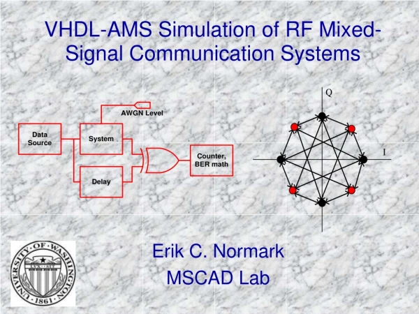
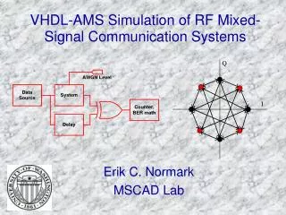
VHDL-AMS Simulation of RF Mixed-Signal Communication Systems Erik C. Normark MSCAD Lab
Outline • Background and Motivation • Design of Mixed-Signal Systems • VHDL-AMS Basics • Design Tools • Simple BPSK Model • System Design • Simulation Results • π/4 DQPSK Model • Basic System Design • Design with Viterbi Encoding • Summary and Conclusions
Design of Mixed Signal Systems • Increasing demand for System-On-Chip • RF, analog, digital circuits all on one chip • Fast time-to-market issues • Less established analog automated design process • Bottom-up design approach common • VHDL-AMS promotes multiple abstraction layers • facilitates mixed design approach • Behavioral model refined until physical transistor-level implementation reached • Promotes re-use of architectural code
Motivation • Create a mixed-signal, system-level model of a high-frequency transceiver in VHDL-AMS • Ability to measure system performance Through Bit-error-rate (BER) analysis • Compare results of VHDL-AMS simulations with other available mixed-signal modeling environments.
VHDL-AMS Language Basics • Extension of VHDL standard • Adds support for DAE’s and conservative quantities • Supports description and simulation of analog, digital, mixed signal, multi-physics devices • Encourages device modeling at various architecture levels (ideal, non-linear, transistor)
Design Tools • ADVance-MS (ADMS) • Compiler and simulator for VHDL, VHDL-AMS, Verilog, Verilog-A, SPICE, C • Supports most of VHDL-AMS standard • No support for file I/O, Procedural, frequency-domain noise • Agilent ADS • Commercial RF design environment for system-level design modeling and simulation
BPSK System • Evaluate system performance via comparison to theoretical BER calculation • Ideal System Architecture • Transmitter • Noisy Channel • Receiver • BER Calculation
How Ideal? • Oscillator: V==10**(A/20.0)*cos(math_2_pi*f*now + Ph); • PA and LNA: vo == vi*10**(gain/20.0); • Mixer: vout==v1 * v2;
BPSK : Transmitter • Modulate data by shifting phase of oscillator between ±180o
BPSK : Propagation Channel • Basic channel with variable Additive White Gaussian Noise Power • Can expand this architecture to include delay spread • Box-Muller transformation of two uniform, independent random variables
WGN Generator Process noise_calc : process (noise_s) variable s1 : positive := seed1; variable s2 : positive := seed2; variable x1,x2 : real; -- Uniform random variables begin UNIFORM(s1,s2,x1); -- create two uniform variables UNIFORM(s1,s2,x2); -- create Gaussian variable using Box-Muller method noise_s <= SQRT(-2.0*LOG(x1))*COS(2.0*MATH_PI*x2) after rate; end process noise_calc; vo == 10.0**(level/20.0)*noise_s;
BPSK : Receiver • Normally Requires coherent detection • Uses original oscillator from transmitter blocks to bypass this requirement • Design verification only
BER Calculation • Good estimate of system performance in the presence of noise • Used Monte Carlo method to measure BER • Sequence of Bernoulli trials • Minimum knowledge of system required
BPSK : BER Calculations Theoretical BER : Pb : Probability of a bit error (BER) ρb : Power level of bit (Eb/No)
Basic π/4 DQPSK System • Ideal System and Architecture • No coherent demodulator required • Less complex receiver implementation • Better spectral characteristics than QPSK, BPSK • Standard for US and Japanese cell phones
π/4 DQPSK : Transmitter • Parallelize Data • Map Symbols • Pulse Shape • Up-convert and amplify
Signal Constellation • Directly map a pair of input bits onto relative phases (±π/4, ±3π/4)
01 00 11 11 Example Transmit: 00111101
Symbol Mapping Code • Uses state machine to implement: • Initial state must be on constellation point
π/4 DQPSK : Receiver • Four Steps: • Amplify and down-convert • Filter • Demodulate and recover symbol clock • Digitize and Serialize
IQ Demodulator Code -- Perform A, B recovery Ip == Ik'delayed(Tsym); Qp == Qk'delayed(Tsym); Atemp == Qk*Qp+Ik*Ip; Btemp == Ip*Qk-Ik*Qp; • To recover parallel data, pass Atemp and Btemp through threshold detector • Digitize, Serialize
Symbol Timing Recovery • Squaring and adding I, Q channels produces tone at symboling frequency • High-Q BPF isolates tone • Threshold detector creates std_logic clock at symbol frequency • transitions in middle of bit period • More complex : feed BPF signal through PLL • more noise-immune
π/4 DQPSK : Viterbi Encoder / Decoder • Added a simple rate 3/10 Viterbi encoder • Decreases BER • Increases design size x2 • Half clock rate and removal of serial to parallel conversion
Viterbi Encoder • Rate 2/3 encoder (K=3) • Operates on 3 input bits and two bits from cleared register • Produces specific 10 output bits • Less complex Decoder
Viterbi Decoder • Implemented as state machine • Makes decision on correct 3-bit output after 10 bits received • Less complex but less error tolerant • Large code size
Summary of Results • Basic coverage of VHDL-AMS language • BPSK design example • Similar results to theoretical and HP-ADS • Verified noise modeling technique • Small, highly ideal model • π/4 DQPSK design • BER closely matches Agilent ADS and theoretical curves • Increased model complexity with encoder / decoder • Verifies that complete system modeling can be easily performed in VHDL-AMS
Extensions of Research • Increase complexity of model to include non-linear effects in subsystems • Add delay-spread model to propagation channel for multi-path simulation • Continue iterative design process
Acknowledgements Special thanks to: Dr. Richard Shi and MSCAD Lab RF group members Pavel Nikitin, Cherry Wakayama, Lei Yang