Download
1 / 6
60 likes | 77 Views
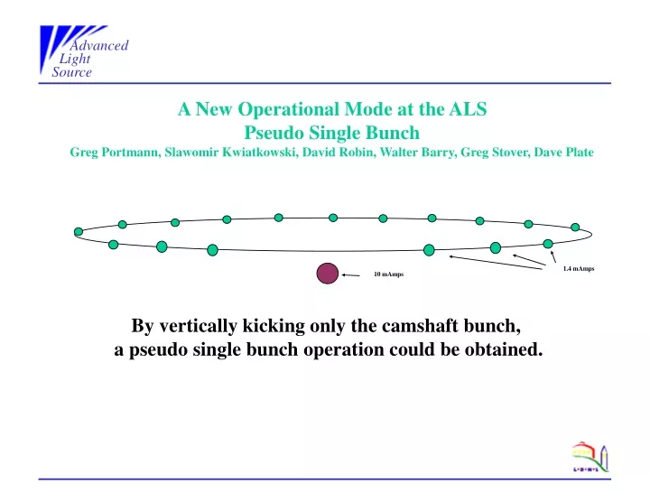
Advanced Light Source. 1.4 mAmps. 10 mAmps. A New Operational Mode at the ALS Pseudo Single Bunch Greg Portmann, Slawomir Kwiatkowski, David Robin, Walter Barry, Greg Stover, Dave Plate. By vertically kicking only the camshaft bunch, a pseudo single bunch operation could be obtained.

E N D
Advanced Light Source 1.4 mAmps 10 mAmps A New Operational Mode at the ALS Pseudo Single Bunch Greg Portmann, Slawomir Kwiatkowski, David Robin, Walter Barry, Greg Stover, Dave Plate By vertically kicking only the camshaft bunch, a pseudo single bunch operation could be obtained.
Advanced Light Source Typically storage ring light sources operate with the maximum number of bunches as possible with a gap for ion clearing. By evenly distributing the beam current the overall beam lifetime is maximized. The Advanced Light Source (ALS) has 2 nanoseconds between the bunches and typically operates with 276 bunches out of a possible 328. For experimenters doing timing experiment this bunch separation is too small and would prefer to see only one or two bunches in the ring. The ALS allocates four weeks every year for dedicated 2-bunch operation. In order to provide more flexible operations and substantially increase the amount of operating time for time-of-flight experimenters, it is being proposed to kick one bunch on a different vertical closed orbit. By spatially separating the light from this bunch from the main bunch train in the beamline, one could potentially have single bunch operation all year round. By putting this bunch in the middle of the ion clearing gap the required bandwidth of the kicker magnets is reduced. Using one kicker magnet running at the ring repetition rate (1.5 MHz), this bunch could be permanently put on a different closed orbit. Single Kicker Magnet Using 1 fast kicker magnet running at 1.5 MHz the camshaft bunch can be permanently put on a different closed orbit. A convenient location of the kicker would be to install it where one of the 3rd harmonic cavities has been removed – approximately 18 meters from the center of straight one. The figures below show the change in the closed orbit for the camshaft bunch for a 60 μradian kick.. As shown in Fig. 1, this configuration would be suitable for a number of beamlines. Many of the dot-1 and dot-4 beamlines and some of the dot-0, dot-2, dot-3 would see a sizeable separation.
Advanced Light Source FIG.1 For transmission line type kicker neglecting the beam transit time factor the minimum value of the potential applied to each electrode (with opposite sign): E-beam energy (1.9GeV) d-aperture(0.015m) Θ-deflection angle (60uRad) l- kicker length (0.6m) WHERE:
Advanced Light Source We have built and tested the pulse amplifier using IXYSDE series RF Power MOSFETs.. We successfully tested this unit up to the full power capabilities. The output 1kV pulse is shown in Fig.2. 10%-90% rise/fall time of the pulse is 8/11ns and the pulse length is 72ns. For 1.5MHz repetition rate power dissipation in the power transistor is about 200W that is well within its power handling capabilities (Pmax<750W). Total dc power for this case is 1600W. Average power delivered to the load is 1400W (20kW peak ). Figure 2 Schematic diagram of the pulse amplifier (positive polarity kick) is shown in Fig.3
Advanced Light Source Fig.3
Advanced Light Source The required cross-section of the kicker (optimized with ANSOFT designer code ) is shown in Fig.3 Fig.3 POWER LOSSES IN EACH KICKER ELECTRODE: 1.)From pulse-300mW(10% DUTY FACTOR 1kV INTO 50Ω) 2.)From Beam image current: multibunch mode -140mW(500mA beam current σ=30ps RMS) Total losses in each electrode<0.5W